7.5.6 Installing the back pull-out unit
✓ The notes and steps stated in (⇨ Section 7.5.1 Page 54) to (⇨ Section 7.5.5 Page
60) have been observed/carried out.
✓ Any damaged or worn parts have been replaced by original spare parts.
✓ The sealing surfaces have been cleaned.
1.
Fit support foot 183.
2. If required, prevent the back pull-out unit from tipping over (e.g. by suspending
or supporting it).
3. Push the back pull-out unit with new gasket 411.10 into pump casing 101.
Make sure that the impeller does not abut the wear plate.
4. Tighten nuts 920.01.
5. Fasten support foot 183 to the baseplate with foundation bolts.
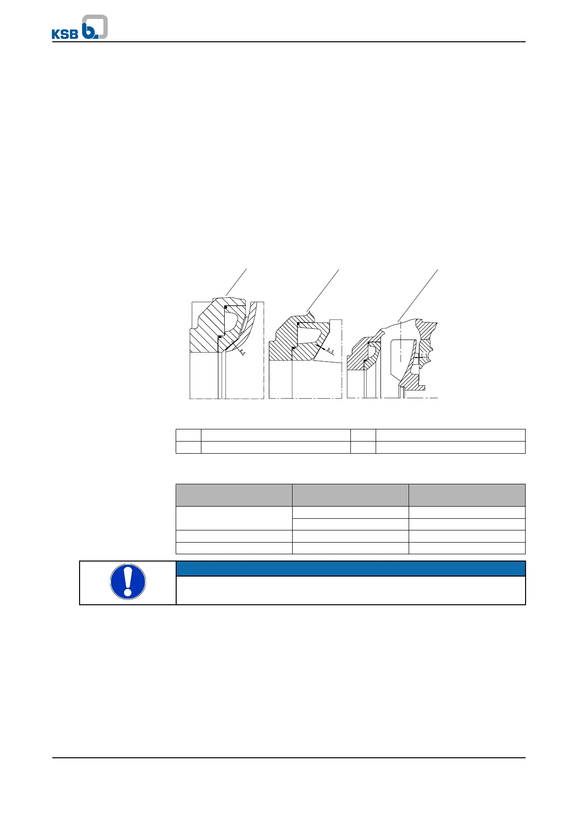
7.5.7 Adjusting the diagonal gap
Fig. 22: KWP clearance gaps
1 Impeller type K 2 Impeller type O
3 Impeller type F
Table 22: Clearance gaps between impeller and casing wear ring / between back
vane and discharge cover
Impeller type Nominal diameter of the
discharge nozzle
Clearance gap
KWP K < DN 300 0.50 mm + 0.1
DN 300 to DN 450 0.60 mm + 0.1
KWP O - 0.50 mm + 0.1
KWP F - 1.50 mm + 0.1
NOTE
If the specified clearance gap is exceeded by more than 0.5 mm, adjust the diagonal gap
as described below.
Closed im p e l l er (KWP K) an d o p en impeller ( K W P O)
✓ The notes and steps stated in (⇨ Section 7.5.1 Page 54) to (⇨ Section 7.5.6 Page
61) have been observed/carried out.
1.
Undo grub screws 904.01 or (for bearing brackets P10ax, P12sx) hexagon head
bolts 901.91.
2. Use socket head cap screws 914.02 to push the bearing carrier together with the
rotor until it abuts wear plate 135.01.
3. Measure the axial clearance between bearing bracket 330 and bearing carrier
382.
7 Servicing/Maintenance
KWP
61 of 78