Note: For other types of coupling, see their instructions
manual.
The equipment must always be aligned after
mounting and preparing for start up, check
that the assembly can rotate freely when operated by hand
5.2.2 Close coupled groups
Levelling
Use a spirit level to level the equipment. Use wedges to alter
the height at different points. The maximum deviation
permitted is 0.2 mm/m.
Pump - motor alignment
The equipment is aligned at factory, and this alignment must
never be lost. The following instructions must be followed
when dismounting or returning the motor:
- Check that the flange support surface of the motor
support and of the motor itself are perfectly clean and
smooth.
- The motor shaft should easily enter the pump shaft (or
bushing). If it does not, do not force assembly as this will
damage the motor bearings. Check the alignment
between both shafts and repair or replace them as
necessary.
5.2.3 Vertical groups
Levelling
Use a spirit level to level the equipment. Use wedges to alter
the height at different points. The maximum deviation
permitted is 0.2 mm/m.
The separation between the two coupling halves must be
maintained.
Pump - motor alignment
In order to prevent misalignment between the shafts, it is
necessary to correctly install, check and maintain the coupling.
See the instructions manual for the coupling.
The coupling may produce a source of ignition or high
temperature in the event of incorrect operation. The
coupling must be classified as non-electric equipment with at
least the same type of area and temperature as the pump. It is
necessary to follow the instructions in the coupling manual
which is included with the pump.
The equipment is aligned at factory, and this alignment must
never be lost. The following instructions must be followed
when dismounting or returning the motor:
- Check that the flange support surface of the motor
support and of the motor itself are perfectly clean and
smooth.
- Check the correct separation between the two halves of
the coupling.
- Check that the alignment between both shafts is correct
by turning the equipment by hand.
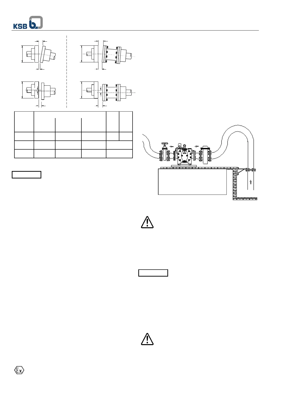
5.3 Pipe joint
In no case can the pump be used as a fixed point for the
pipes.
The pipe system must at no time exercise force in
excess of the values shown in the chart in point 4.4
(due to connection, thermal variation, etc) in the
pump.
The short pipes must be of at least the diameter of the pump
connections. The diameter of long pipes is, in some cases,
determined by economic criteria.
Transition pieces at larger diameters must have an extension
angle of around 8°, in order to prevent pressure drops.
The convenience of installing foot valves
when the pump is working in suction or
retention when loaded, along with seal valves, will depend on
the type of installation.
The thermal expansions of the pipes must be compensated
with suitable measures, in order not to exceed the maximum
strains permitted on the pump.
The diameters of the pipes, valves and accessories must be
calculated in line with the load losses envisaged in the
installation, meaning the fluid speeds will be suitable for the
circuit and the viscosity of the fluid.
Exceeding the admitted strains of the pipes may lead
to leaks in the pump and to the fluid escaping.
Hazard of death with hot liquids!
When designing the suction piping check that the available
NPSH is higher than required NPSH of the pump in order to
avoid cavitation in whole admissible operation range.
The suction and impulsion nozzle covers of the pump must be
removed before connecting the pipes.
 Loading...


