Part No. Comprising Description
922.01 922.01 Impeller nut
99-9
25)
99-9
25)
Set of sealing elements, complete
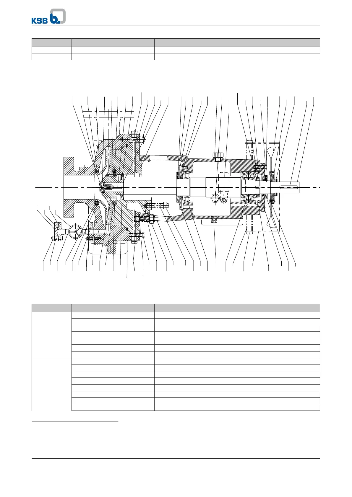
9.1.2 Bearing brackets B06 and B07
D01042/3
931.02
260
550.87
906
411.31
503.01
502.01
102
904.07
904.04
940.01
904.38
916.16
902.01
920.01
161
904.41
330
914.01
400.01
360.01
913.03
411.32
642
169-10
638
931.01
920.21
901.37
831.02
904.42
412.22
904.37
210
485.02
940.02
901.20
920.20
710.21
904.03
724.01
723.21
411.41
744.07
550.20
230
904.06
723.23
902.42
550.42
920.42
411.01
503.02
502.02
542.02
411.10
916.18
916.19
412.01
901.30
412.31
902.15
920.02
901.31
920.15
902.02
320.02
322.01
916.46
525.09
507.01
832
550.74
904.43
901.80
360.02
507.02
901.84
a)
b)
Fig. 17: Bearing brackets B06 and B07, a) uncooled and b) cooled
Table 26: List of components for pumps sets with bearing brackets B06 and B07
Part No. Comprising Description
102 102 Volute casing
411.10 Joint ring
502.01 Casing wear ring
902.01 Stud
904.03 Grub screw
916.01
39)
Screw plug
920.01 Hexagon nut
161 161 Casing cover
411.10 Joint ring
412.01/.31
40)
O-ring
502.02
41)
Casing wear ring
901.30 Hexagon head bolt
902.15 Stud
904.04
41)
Grub screw
916.16 Screw plug
39)
Not shown in drawing
40)
For cooled design only
41)
For impellers with balancing of axial thrust only
9 Related Documents
RPH
67 of 76