WKT
10
5. Installation at site
Pumps should be installed, leveled and aligned by
qualified people. When this service is inappropriate
executed, it can have as consequence, operation
troubles, premature wear and irreparable damage.
Foundation Plan drawing (FU) informs pump dimension,
weights, foundation arrangement, connection sizes and
position of fixation elements.
Assure that all parameters for handling and operation
(access, assembly area, connections for assembly
equipment, cranes, etc) were perfectly established before
pump installation activities.
5.1 Safety regulations
Equipment operated in hazardous locations
must comply with the relevant explosion
protection regulations. This is indicated on the pump
name plate and motor name plate (see 2.9).
5.2 Checks to be carried out prior to installation
All structural work required must have been prepared
in accordance with the dimensions stated in the
dimension table / general arrangement plan.
In case of concrete foundations they shall have
sufficient strength (min.class X0) to ensure safe and
functional installation in accordance with DIN 1045-2
or equivalent standards.
Make sure that the concrete foundation has set firmly
before placing the unit on it. Its surface shall be truly
horizontal and even. The foundation bolts shall be
inserted in the soleplate.
5.2.1 Place of installation
The distributor casing, the pipe assembly and
certain areas of the soleplate take on roughly the
same temperatures as the medium handled. The motor
stool or bearing bracket lantern must not be insulated.
Take the necessary precautions to avoid burns.
5.3 Foundation
A special base frame must be fitted flush on shims in the
foundation or cover aperture to receive the pump set. The
concrete base must have set before the base frame is
fitted.
Carefully level the machined seating face for the barrel
flange using a precision spirit level; use stainless steel
shims to compensate for any differences in height.
Do not grout and concrete in the base frame until the
pump set has been installed and the levels rechecked.
5.4 Barrel cleaning
Before mounting of barrel in the pit clean carefully inner
side of the barrel, keeping it horizontally and tilting it as
and when required till it is absolutely cleaned up.
5.5 Mounting
Fit the barrel separately in the leveled base frame,
carefully align and secure on the base frame.
Fit and align pump set and driver as described in section
5.6.
Then concrete in the base frame; re-check the alignment
and secure the barrel flange to the base frame using
studs and nuts.
5.6 Aligning the pump / drive
The pump unit consisting of pump, coupling and drive has
been mounted on a common set and is carefully aligned
in the manufacturing works.
The following instructions also apply to units not mounted
on a common set.
After connecting the piping and priming
the system, it is essential to re-check
the alignment at operating temperature.
Incorrect alignment and inadmissible
coupling displacement will affect the
operating behavior and may result in damage to the
bearings and shaft seals as well as premature coupling
wear.
Please note:
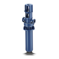
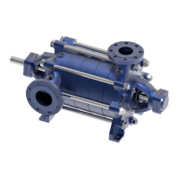
The pump set is correctly aligned, if a straight-edge
placed axially on both coupling halves is the same
distance from each shaft at all points around the
circumference. In addition, the distance between the two
coupling halves must remain the same all around the
circumference. Use a feeler gauge, a wedge gauge or a
dial micrometer to verify (see figs. 10 and 11).
Fig. 10 - Aligning the coupling with the help of a gauge
and a straight-edge
Fig. 11 - Aligning a spacer-type coupling
The radial and axial deviation between the two coupling
halves must not exceed 0, 1 mm.
The alignment of the pump and drive shall preferably be
checked by means of a dial micrometer. For this purpose
Caution
Caution