WKT
12
6. Commissioning, start-up / shutdown
Compliance with the following
requirements is of paramount
importance. Damage resulting from non-compliance shall
not be covered by the scope of warranty.
6.1 Preparations
6.1.1 Recommended safety instrumentation for pump
a) Level switch for low level in suction tank.
b) Differential pressure indicator with switch across the
suction strainer.
Both these instruments should give trip signal for motor.
6.1.2 Lubrication
Check the bearing lubrication and correctly fill with the
specified amount of lubricant. See 6.1.4 for lubricant fill
and quality.
6.1.3 Pre-commissioning checks
a) Flushing of suction tank, suction pipeline with water
after chemical cleaning. Take care to blind the pump
suction and discharge nozzles before flushing;
b) Cleaning of suction strainer;
c) Barrel cleaning; see 5.4;
d) Shaft seal;
I) Check shaft seal and pack as described in
6.1.5.1 (applicable for gland packing execution
only);
II) Remove auxiliary piping for mechanical seal ie.
cooling, flushing, quenching, etc. It must be
thoroughly cleaned with water, dried and then
refitted.
e) Fit suction and discharge pressure gauges;
f) Check functioning of all interlocks by stimulation
method;
g) Priming – see 6.1.6 for details;
h) Check free rotation of shaft manually.
6.1.4 Lubrication
Oil lubrication
The support bearing is lubricated by the oil fill in the
bearing housing (350). An oil elevator tube (646) inside
the centering sleeve (526) supplies oil to the antifriction
bearing. The requisite oil level is maintained by a
constant level oiler (638). The reservoir of this constant
level oiler must therefore always be kept topped up with
oil.
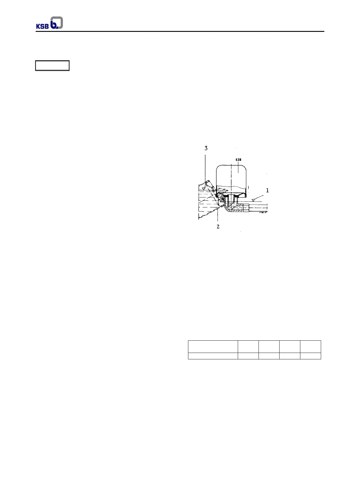
Filling and topping up (see fig. 13).
Filling and topping
Remove the protective case of the constant level-oiler.
Unscrew vent plug. Pour in the oil through the vent plug
tapping hole after having removed out the reservoir of the
constant level oiler until oil appears in the vertical portion
of the connection elbow. Then fill the reservoir of the
constant level oiler with oil and snap it back into operating
position. Screw vent plug in again. After a short time
check whether the oil level in the reservoir has dropped. It
is important to keep the reservoir properly filled at all
times.
The oil level should always be below the level of the vent
opening arranged at the top edge of the connection
elbow.
1. Oil level in bearing housing and in connection elbow.
2. Position for topping up of oil level make-up quantity.
3. Oil level in oil reservoir after filling of same.
Oil changes and oil requirements
The first oil change should take place after the first 300
hours of operation, and subsequent oil changes should
be effected after every 3000 hours of operation, but at
least once a year.
Unscrew and remove the drain plug (903.4) on the
bearing housing and drain the oil. After draining of the
bearing housing, replace the drain plug and fill in fresh oil.
Pump sizes 40 50
65
80
100
125
150
Oil fill
ltrs 0,3 0,5 0,6 1,2
1)
Oil filling quantity (including constant level oiler and filler
pipe).
Fig. 14 Oil requirements
Oil specification
The oil used should exhibit the following characteristics:
Kinematics viscosity at 50ºC = 30 to 45 mm
2
/s
Density at 20ºC = 0,9 kg/dm
3
Flash point = at least 150ºC
Pour point = below -5ºC
Ash content = not exceeding 0,05%
Neutralization number = not exceeding 0,3
Asphaltenes = 0%
Caution
Fig.13 - Filling with oil