WKT
11
remove the coupling spacer after having marked its
installation position by dotting marks (balancing
condition).
At the same time check the motor´s direction of rotation,
with the pump decoupled (see 6.1.7). The direction of
rotation must correspond to the direction indicated by the
arrow on the pump. Verify by switching the motor on and
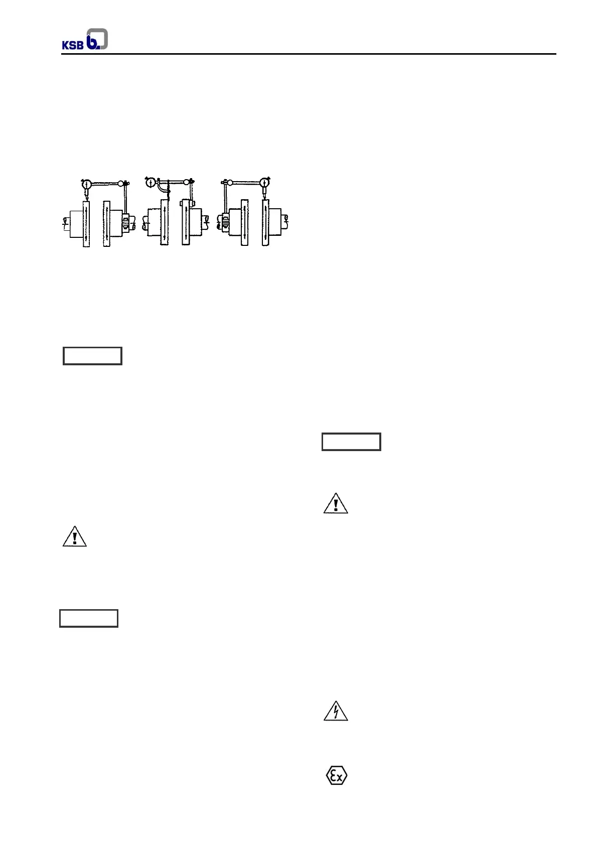
then off again immediately. Fig. 12 ilustrates examples of
possible dial micrometer arrangements.
Fig. 12 - Aligning a spacer-type coupling with a dial
micrometer
Admissible run-out of coupling face (axial) max. 0,1 mm.
Admissible radial deviation, measured over the complete
circumference, max. 0,2 mm.
5.7 Connecting the piping
Never use the pump itself as an
anchorage point for the piping. The
permissible pipeline forces must not be exceeded (see
section 4.3.5).
The pipelines shall be anchored in close proximity to the
pump and connected without transmitting any stresses or
strains. The nominal diameters of the pipelines shall be at
least equal to the nominal diameters of the pump nozzles.
It is recommended to install check and shut-off elements
in the system, depending on the type of plant and pump.
It must be ensured, however, that the pump can still be
drained and dismantled without problems.
Thermal expansions of the pipelines must be
compensated by appropriate measures so as not to
impose any extra loads on the pump exceeding the
permissible pipeline forces and moments.
An excessive, impermissible increase in the
pipeline forces may cause leaks on the pump
where the fluid handled can escape into the atmosphere.
Danger of life when toxic or hot fluids are handled!
The flange covers on the pump suction and discharge
nozzles must be removed prior to installation in the
piping.
After the piping has been connected, it
must be easy to rotate the pump shaft by
hand at the coupling.
Recommendations for suction
In the pump installation, please consider the following
conditions:
a) Check minimum distance from bottom well up to
suction outlet or strainer according to installation (see
foundation plan).
b) Check liquid minimum level above pump casing, in
order to avoid dry operation, cavitation or vortex.
c) In case of frequent liquid level variation, it should
foreseen the installation of protection system against
operation below the minimum level.
d) In case of liquid with solids in suspension or with
excessive dirty, it should foreseen strainer in the pump
inlet.
Recommendations for discharge piping
The discharge piping assembly should comply with the
following considerations:
a) It should have disposals for water hammer control,
every time the overpressure values, deriving from liquid
return in long pipings, exceeds the recommended values
for piping and pump.
b) In the points where it is necessary to extract the air it
should foreseen vent valves.
c) It is necessary to foreseen tie bolted assembly joints, to
absorb system reaction efforts, deriving from applicable
loads.
d) Safety valves, relief disposals and other operation
valves, besides those mentioned, should foreseen when
necessary.
5.7.1 Auxiliary connections
The dimensions and locations of the auxiliary
connections (cooling, barrier liquid, flushing liquid, etc.)
are indicated on the general arrangement drawing or
piping layout.
These connections are required for proper
functioning of the pump and are therefore
of vital importance!
5.7.2 Coupling guard
In compliance with the accident prevention
regulations the pump must not be operated
without a coupling guard.
If the customer specifically requests not to include a
contact guard in our delivery, then the operator must
supply one. In this case, it is important to make sure that
the materials selected for coupling and coupling guard
are non-sparking in the event of mechanical contact.
KSB’s scope of supply meets this requirement.
5.8 Final check
Re-check the alignment as described in section 5.6 and
verify the correct distance between the coupling and the
coupling guard.
It must be easy to rotate the shaft by hand at the
coupling.
5.9 Connection to power supply
Connection to the power supply must be effected
by a trained electrician only. Check available
mains voltage against the data on the motor rating plate
and select appropriate start-up method.
We strongly recommend to use a motor protection device
(motor protection switch).
In hazardous areas, compliance with IEC60079-
14 is an additional requirement for electrical
connection.
Caution
Caution
Caution


 To Next Page