WKT
28
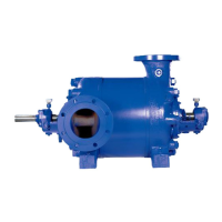
Pump with impeller wearing rings and interstage
bushes (see fig.01)
Pump sizes 40 to 150, pressure rating 20/40.
Supplements for sections:
Examination of individual components
Pump Body
Suction casing (106), discharge casing (107), stage
casings (108), impellers (230,231), impeller wearing
rings (503), casing wearing rings (502), interstage
bushes (541), distance bushes (521), or sleeves (520)
with pump size 150.
Ensure all the sealing faces are in perfect condition.
Check the plane parallelism of the faces at 4 points on
the circumference with a micrometer. The deviation must
not exceed 0,02mm. Damaged faces can be machined
on a lathe.
The surface roughness must not exceed 0, 8 microns.
The impellers (230, 231), stage casings (108), and
diffusers (171), are fitted with renewable wearing parts –
impeller wearing rings (503), casing wearing rings (502),
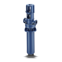
and interstage bushes (541). Check the wearing parts for
galling and check the rotor clearances per figs. 5 and 6.
The wearing parts must only be machined when fitted
and the maximum permissible clearances must be
respected. Any increase in clearance must be made
uniform at all wearing parts inside the pump.
Fig. 01 Full Chrome design with impeller wearing rings
and interstage bushes, pressure rating 20/40.
If the rotor clearances are the same as or greater than
the max. permissible clearances specified in figs. 5 and
6, fit new oversizes wearing parts and reestablish the “as
new” clearances.
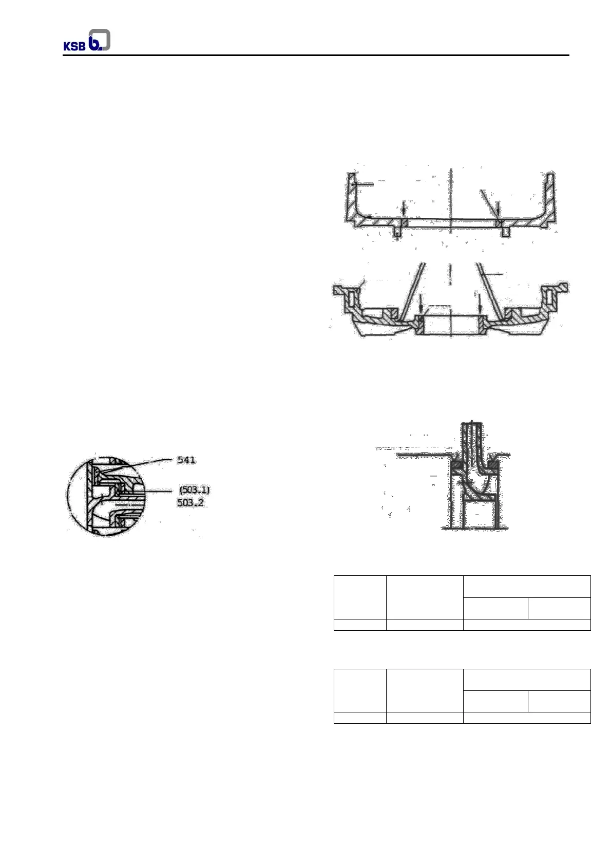
Fitting new casing wearing rings (502):
1. Undo the allen grub screw, press the casing wearing
rings in the stage casing and diffuser out of the fit,
taking care not to damage the fit (see fig. 02).
2. Uniformly, press new oversized casing wearing
rings (normally 2 mm allowance) into the bore
(cooling the rings makes this easier).
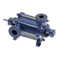
3. Smooth down all impellers (230, 231) in the region
of the fitted impeller wearing rings (503) to a
common diameter, basing this on the most heavily
scored impeller wearing ring. Single deep grooves
can be left untouched (see fig. 03).
4. Calculate the average actual diameter of all
smoothed down impeller wearing rings. Adding this
to the “as new” clearance per figs. 4 and 5 gives the
bore diameter for the casing wearing rings,
tolerance + 0,04mm.
Fig. 02 Renewing the casing wear rings and stage
bushes
5. Align the stage casing (108) and diffuser (171) with
fitted casing wearing ring to the outer fit and
machine the wearing ring without changing setting.
Fig. 03 Smoothing out the throttle sections on the
impeller wearing rings.
Clearances
Pump sizes
Operating
temperature ºC
Clearances for material
combination
0,6
“as new”
1,2
max. perm.
40 to 150 0 to +200 AISI 420/AISI 420 (Hard)
Fig. 04 Impeller wearing ring / casing wearing ring
clearances; mm on Ø
Pump sizes
Operating
temperature ºC
Clearances for material
combination
0,6
“as new”
1,2
max. perm.
40 to 150 0 to +200 AISI 420/AISI 420 (Hard)
Fig. 05 Distance bush / interstage bush clearance, mm
on Ø
Supplementary sheet
smooth here
Diffuser
Stage casing
Casting wearing ring
Shim
Lever
Inter stage
bush