WKT
20
7.4.3.7 Dynamic balancing of pump rotor
For this purpose, the pump rotor should be assembled as
follow:
Assembly proceeds from the front end; slip stage sleeve
(521) onto pump shaft (211) until it abuts against the shaft
shoulder. Insert the key and slip final stage impeller (230)
onto the shaft until it abuts.
Mount the stage sleeve (521) (sleeve (520), on pump size
150), - keys and impellers (230) of the remaining stages
in sequence, as described above. Fit the split ring (501)
and key (940.2). Push on the stage sleeve (529.1) and
suction impeller (231).
N.B. The impellers must be mounted in their correct stage
sequence.
Slip on lock washer (931.1) and clamp the mounted
components together on pump shaft (211) with the aid of
shaft nut (920.2).
Place the bearing sleeve and fix it with the circlip 932.1.
Before dynamic balancing, the rotor should be checked for
true running (out-of-round) at the impellers (230) and at
the bearings. The measured out-of-round value must not
exceed 0,03mm. The rotor should then be balanced
dynamically at max. pump operating speed if possible but
at least at 1000 1/min. The max. permissible residual
eccentricity must not exceed 5 µm (micron meter). Before
final assembly in the pump, the pump rotor must be
dismantled again in reverse sequence to the assembly
procedure described above.
7.5 Reassembly
7.5.1 General instructions
The pump shall be reassembled in accordance with the
rules of sound engineering practice.
Clean all dismantled components and check them for
signs of wear. Verify the dimensions given in fig. 18, 19 e
and 20. Damaged or worn components are to be replaced
by original spare parts. Make sure that the seal faces
are clean and that the sealing elements are properly
fitted.
Always use new sealing elements (O-rings / gaskets)
whenever the pump is reassembled. Make sure that new
gaskets have the same thickness as the old ones.
Gaskets made of graphite or other asbestos-free
materials must always be fitted without using lubricants
such as copper grease or graphite paste.
Avoid the use of mounting aids as far as possible. Should
a mounting aid be required after all, use a commercially
available contact adhesive (e.g. “Pattex”). The adhesive
shall only be applied at selected points (3 to 4 spots) and
in thin layers.
Do not use cyanoacrylate adhesives (quick-setting
adhesives)! If in certain cases mounting aids or anti-
adhesives other than described herein are required,
please contact the sealing material manufacturer.
All graphite gaskets must only be
used once!
Never use O-rings that have been glued together from
material sold by the metre.
7.4.3.6 Rotor and bearing clearances
Pump sizes
Operating
temperature ºC
Clearances mm on
for material combination
0,4 1,0 0,6 1,2
“as new” max. perm. “as new” max. perm.
40 to 150 0 to +200
Cast iron / Cast iron AISI 316 / AISI 316
12% Cr / 12% Cr
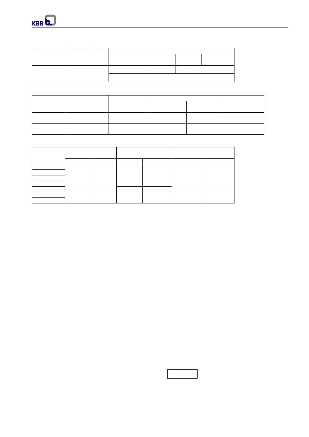
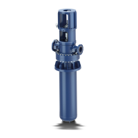
Fig. 19 Impeller / Casing wearing ring clearance.
Pump sizes
Operating
temperature ºC
Clearances mm on
for material combination
0,4 1,0 0,6 1,2
“as new” Max. perm. “as new” Max. perm.
40 to 150 0 to +105
Cast iron / Cast iron
Carbon Steel
AISI 316 / A743CF8M
12% Cr / 12% Cr
40 to 150 +106 to +200 -
Cast iron / Cast iron
12% Cr / 12% Cr or Carbon Steel
Fig. 19a Stage sleeve / diffuser clearance.
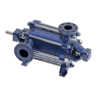
Pump size
Bearing 1
s
stage
diffuser
Bearing in discharge
casing
Intermediate shaft bearing
Min. Max. Min. Max. Min. Max.
40
0,040 0,106
0,050 0,128
0,050 0,128
50
65
80
100
0,060 0,152
125
0,050 0,128 0,060 0,152
150
Fig. 20 Plain bearing clearance (in mm referred to Ø).
Caution