WKT
8
Arragement drawing (examples)
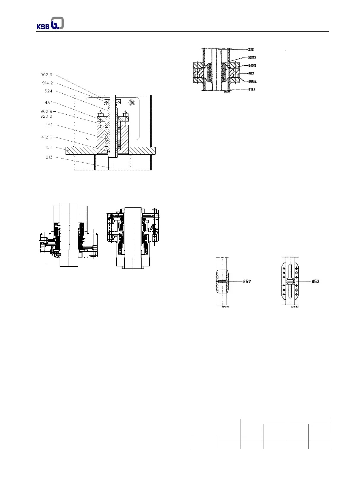
Gland packing (special variant-consult KSB to use in
explosive atmospheres)
Fig. 02
Mechanical seal
4.3.4 Bearing arrangement
4.3.4.1 Pump bearings
The pump shaft runs in two plain bearings.
The bearing at the suction end is arranged in the suction
casing (106) and the bearing at the discharge end is
arranged in the discharge casing (107). Both these
bearings are lubricated by the product pumped.
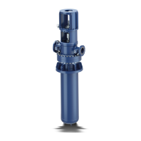
4.3.4.2 Intermediate shaft bearings
(See fig. 05)
The intermediate shafts are guided by bearing spiders
(383) with built-in bearing bushes (545.3) between the
lengths of column pipe. Their construction and lubrication
corresponds to that of the pump bearings.
Fig. 05 Intermediate shaft bearing
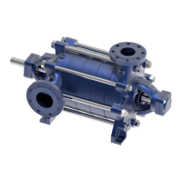
4.3.4.2.1 Rigid Couplings for intermediate shafts
Depending on the shaft diameter, rotational speed,
switching frequency and type of driver, either rigid
screwed couplings, or split (muff) couplings are used to
connect the intermediate shafts to one another and to
transmit the driving torque.
In order to prevent the unscrewing (slackening) of
screwed couplings during reverse rotation pumping sets
fitted with such couplings must be provided with a reverse
rotation stop device.
Hollow shaft motors and hollow shaft bevel gears are
equipped with such a reverse rotation stop device.
Electric motors of V1 type series are however not so
equipped, and the direction of rotation of such motors
should therefore be checked before connection to the
shafting. It is therefore preferable to use split (muff)
couplings in conjunction with V1 type series electric
motors. The type of coupling applying to your installation
can be ascertained from the data sheet attached to the
Order confirmation.
See figures below for construction and arrangement.
Screwed coupling Split (muff) coupling
4.3.4.3 Thrust bearing
(See fig. 07 and 08 for construction).
The thrust bearing arranged in the motor lantern absorbs
the weight of the complete pump rotor, including the
weight of the intermediate shafts (212) and drive shaft
(213), and the radial forces which arise, it also absorbs
the residual axial thrust generated, and transmits all these
weights and forces to the motor lantern. Depending on
the values 3 different configurations are available. See
fig. 06. The bearing is oil lubricated, in the normal
execution.
Oil mist lubrication is possible, however it is special and
made up on consult.
Fig. 06
Pump sizes
40 50 and 65
80 and
100
125 and
150
Thrust
bearing
constructions
VÖR 6311 6312 6315 6317
VÖQJ 311 312 315 317
VÖB 25 (7311) 35 (7312) 45 (7315) 60 (7318)
Mechanical seal
Single-acting
Fig. 03
Mechanical seal
Double-acting
Fig. 04
212 Intermediate shaft
383 Bearing spider
400.2 Flat gasket
529.3 Bearing sleeve
545.3 Bearing bush
711.1 Riser pipe