WKT
13
Lubrication by product pumped
The pump bearings and intermediate shaft bearings are
lubricated directly by the product pumped (suction side
bearing by inlet pressure and intermediate shaft bearings
by liquid at pump discharge pressure). No special
maintenance of these bearings is necessary, but the
pump must not be allowed to run dry.
6.1.5 Shaft seal
6.1.5.1 Gland packing
Gland packings supplied with the pump
have to be installed prior to pump startup
(unless they were fitted prior delivery).
The gland packing must be tightened gently and evenly.
It must be easy to rotate the shaft by hand.
a) Fitting new packing
Thoroughly clean the packing compartment and the shaft
protection sleeve, and coat them with molybdenum
disulphide. Insert neck ring (457), if any, and press it
home until it abuts. Insert the packing rings individually
and push them home with the aid of the stuffing box gland
and the seal cage ring. The ring butt of each packing ring
should be offset 90º in relation to the joints of the
adjoining rigid. In case of lubrication by an external
source insert seal cage ring (458) so that it registers
opposite connection 10E.
Then insert the remaining packing rings individually.
Leave a sufficient clearance gap at the entrance of the
stuffing box for the positive guidance of the gland. The
inserted packing rings should only be lightly compressed
by the gland and the nuts.
Then the nuts should be slackened and tightened again
by hand. The even seating of the gland should be
checked with a feeler gauge, with the pump subjected to
suction pressure.
b) Removing the packing
Slacken clamping ring (184) and remove it from shaft
protection sleeve (524), undo stuffing box gland (452) and
pull it out of stuffing box housing.
Pull the top packing rings out of stuffing box housing
(451) with the aid of a packing ring extractor, pull out seal
cage ring (458), if any, then remove the remaining
packing rings and examine shaft protection sleeve (524)
for signs of damage.
Clean the packing compartment and coat it with
molybdenum disulphide.
Pack the stuffing box as described under a) above.
N.B.
The stuffing box should drip slightly whilst the pump is
running the leakage rate should amount to between 2 and
3 l/h. If your pump has sealing and cooling liquid
connections in use, they should be checked for
unimpeded flow. When the stuffing box gland has been
repeatedly tightened in service until it abuts, it is time to
renew the packing in the stuffing box.
Packing material
When selecting the packing material, remember to
ascertain its compatibility with the product pumped.
Always use new packing material, preferably material
which has been stored for a certain period, to repack the
stuffing box.
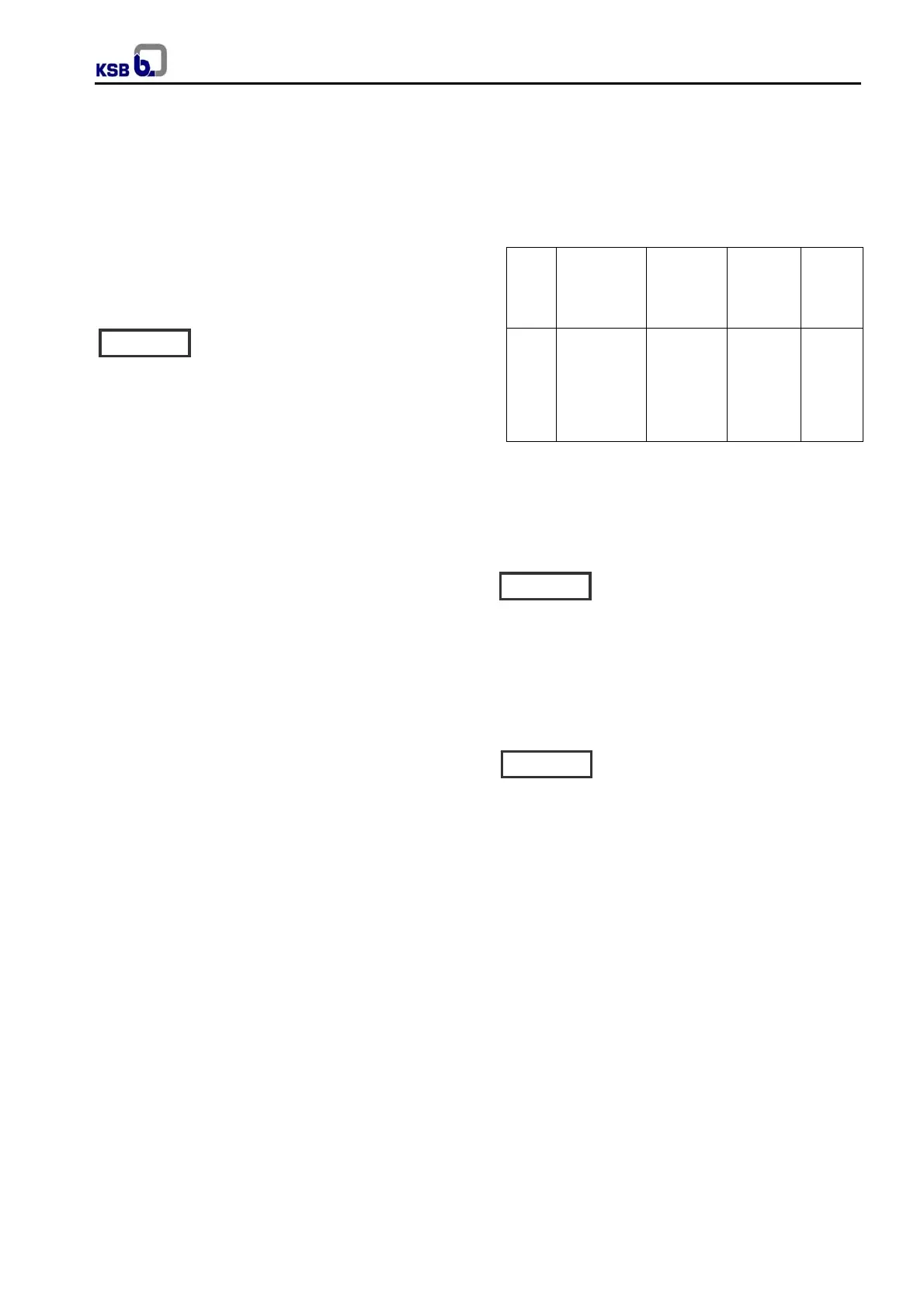
Pump
sizes
Packing
compartment
dws / da
mm
Number of
packing
rings
Width of
packing
mm
Overall
length
mm
40
50
65
80
100
125
150
40 / 60
45 / 70
45 / 70
55 / 80
55 / 80
80 / 112
80 / 112
6
6
6
6
6
5
5
10
12,5
12,5
12,5
12,5
16
16
1400
1500
1500
1600
1600
1800
1800
dws = Outer diameter of shaft protection sleeve
da = Inner diameter of packing compartment
Fig. 15 Dimension of packing compartment and packing.
6.1.5.2 Mechanical seal
The mechanical seal has been fitted prior
to delivery. On variants with quench
supply tank, the tank must be fitted in accordance with
the general arrangement drawing (see also 6.1.6).
Quench feed must also be provided during pump
shutdown. On variants with pressurized dual mechanical
seals, apply barrier pressure as specified in the general
arrangement drawing prior to starting up the pump (see
6.1.6). Barrier pressure must also be provided during
pump shutdown.
For external liquid supply, the quantities
and pressure specified in the data sheet
and general arrangement drawing shall be applied.
6.1.6 Priming the pump and checks to be carried out
The barrel must be filled at all times with product.
The pump body must be vented through the discharge
pipe during priming before commissioning.
6.1.6.1 Vacuum balance line
If the pump has to pump liquid out of a vessel under
vacuum it is advisable to install a vacuum balance line.
The suction area (barrel and distributor casing) is vented
via a line which remains open all the time. This line
should have a nominal size of 25 mm minimum. It should
be arranged to lead back into the vacuum vessel in
vapour phase.
Caution
Caution
Caution
 Loading...