1.7.1 Cable Box Part
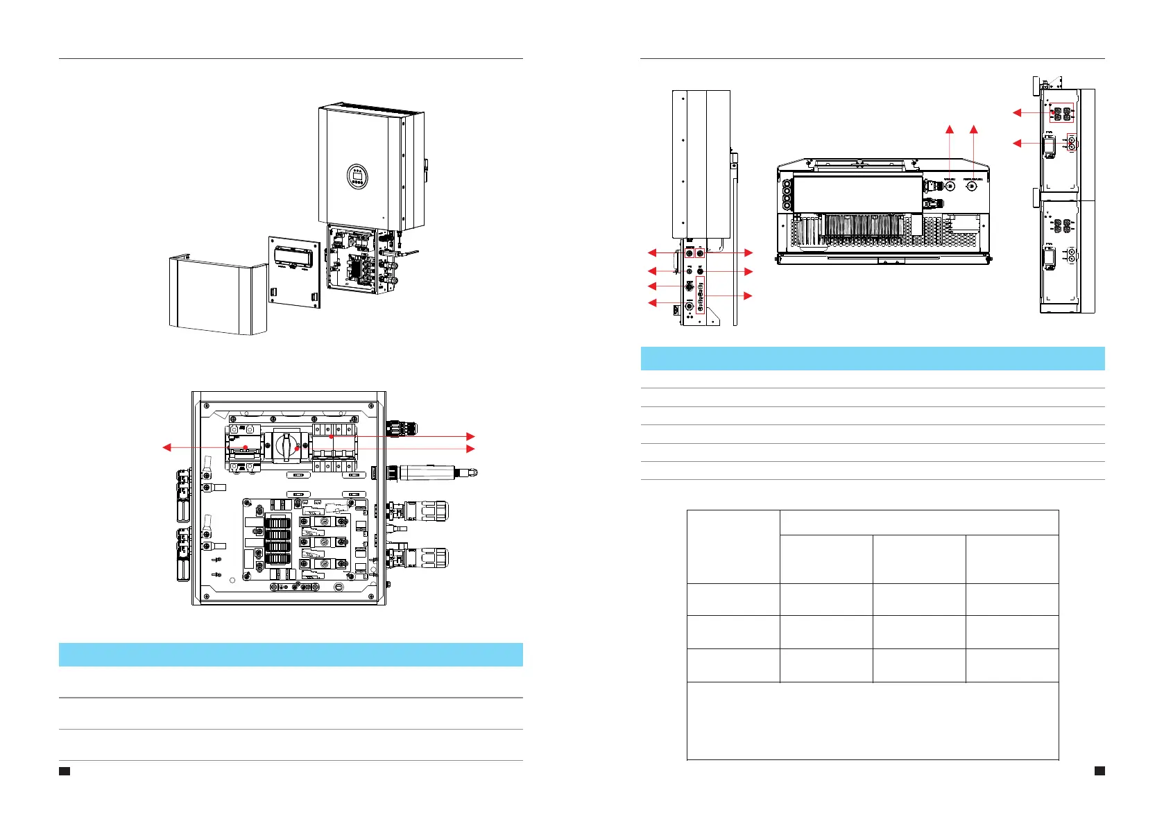
Figure 5 Inverter without Cable Box Covers– Front View
Figure 6 Cable Box Part without Covers – Front View
15
16
1
2
3
Battery circuit breaker
DC isolation switch
Output terminal block(BACK UP)
Object
Description
User Manual User Manual
3
2
1
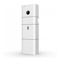
PV1, PV2
1
ON GRID
2
BACKUP
3
DRM OR PARALLEL24
COM
5
METER+DRY
6
BAT
7
BAT+,BAT-
8
DVC C DVC C
DVC C DVC A
DVC A DVC A
DVC A DVC A
Description Description
Object Object
DVC class DVC class
Figure 7 Cable Box Part without Covers
3
2
1
5
8
9
COMM
9
DVC A
6
7
4
10
10
CT DVC A
11
PARALLEL111
DVC A
Note: The DVC indicates the minimum required level of protection for the circuit.
Decisive voltage
Classification
(DVC)
a.c. voltage
r.m.s.
U ACL
a.c. voltage
peak
U ACPL
d.c. voltage
mean
U DCL
Limits of working voltage
V
A*
B
C
≤25
(16)
50
(33)
>50
(>33)
≤35.4
(22.6)
71
(46.7)
>71
(>46.7)
≤60
(35)
120
(70)
>120
(>70)
The table values in parentheses are to be used for PCE or portions of PCEs rated
for installation in wet locations as addressed in 6.1 for environmental categories
and minimum environmental conditions.
*DVC-A circuits are allowed under fault conditions to have voltages up to the DVC-
B limits, for maximum 0.2 s.