● ●
● ● ● ●
1
Operation
Fault
Description
OFF
Normal
Low SoC
Alarm
Hibernation
Off Off Off Off Off Off All off
1
Off
Indicates battery SoC level
Idle state(Current = 0)
Charge
OffOn
Indicates battery SoC level
Indicates battery SoC level
Indicates battery SoC level
Normal(Current > 0)
Discharge
Idle
Module over voltage
Module Under voltage
Cell over voltage
Cell under voltage
Charge MOS fault
Discharge MOS fault
Cell over temperature
1
3
3
3
3
3
3
2
Off
Off
Off
Off
Off
Off
On
On
On
On
Off
Off
On
On
On
On
On
On
On
Off
On
Off
On
On
Off
On
Module low voltage alarm
(SOC<5%)Only in Idle Mode
Cell under
temperature
Charging Over
Current
Discharge Over
Current
Cell sampling fault
Heating fault
Low SoC
Temperature sensor
malfunction
Battery Cell
malfunction
Communication
failure
3
3
3
3
3
3
3
3
3
Off
Off
Off
Off
Off
Off
Off
Off
Off
Off
Off
Off
Off
Off
Off
Off
Off Off
On OnOn
On On
Off
On
On
Off
Off
Off
Off
Off
Off
Off
Off
Off
Off
Off
UserManual UserManual
41
42
On
Normal(Current < 0)
0x340 BYTE 2,3 BIT2
(Vmodule > 57.6V)
0x340 BYTE 2,3 BIT3
(Vmodule < 44.8V)
0x340 BYTE 2,3 BIT0
(Vcell > 3.6V)
0x340 BYTE 2,3 BIT1
(Vcell < 2.8V)
0x340 BYTE 6,7 BIT0
(Still have charge current ,when
charge MOS is turned off)
0x340 BYTE 6,7 BIT1
(Still have discharge current ,
when discharge MOS is turned off
)
0x340 BYTE 2,3 BIT8 and 9
(Tcell > 55℃)
0x340 BYTE 2,3 BIT10 and 11
(Charge Tcell < 7℃ ,
Discharge Tvell < -18℃)
0x340 BYTE 2,3 BIT4
(Current > 95A)
0x340 BYTE 2,3 BIT5
(Current > 95A)
0x340 BYTE 6,7 BIT3
(BMS Internal fault)
0x340 BYTE 6,7 BIT6
OR 0x340 BYTE 4, 5 BIT15
(BMS Internal fault)
0x340 BYTE 2,3 BIT15
(SOC<5%)
In Discharge and Idle Mode
0x340 BYTE 6,7 BIT2
(BMS Internal fault)
0x340 BYTE 6,7 BIT4
(voltage difference between
cells exceeds 1V)
On
0x340 BYTE 6,7 BIT5
(BMS Internal fault)
Physical Picture of Lamp
SOC Low --------------- > High
Idle
Off On
Off Off
3
O ff On On O ff On
On
Off
On
Off
OnOn
On
E
F
G
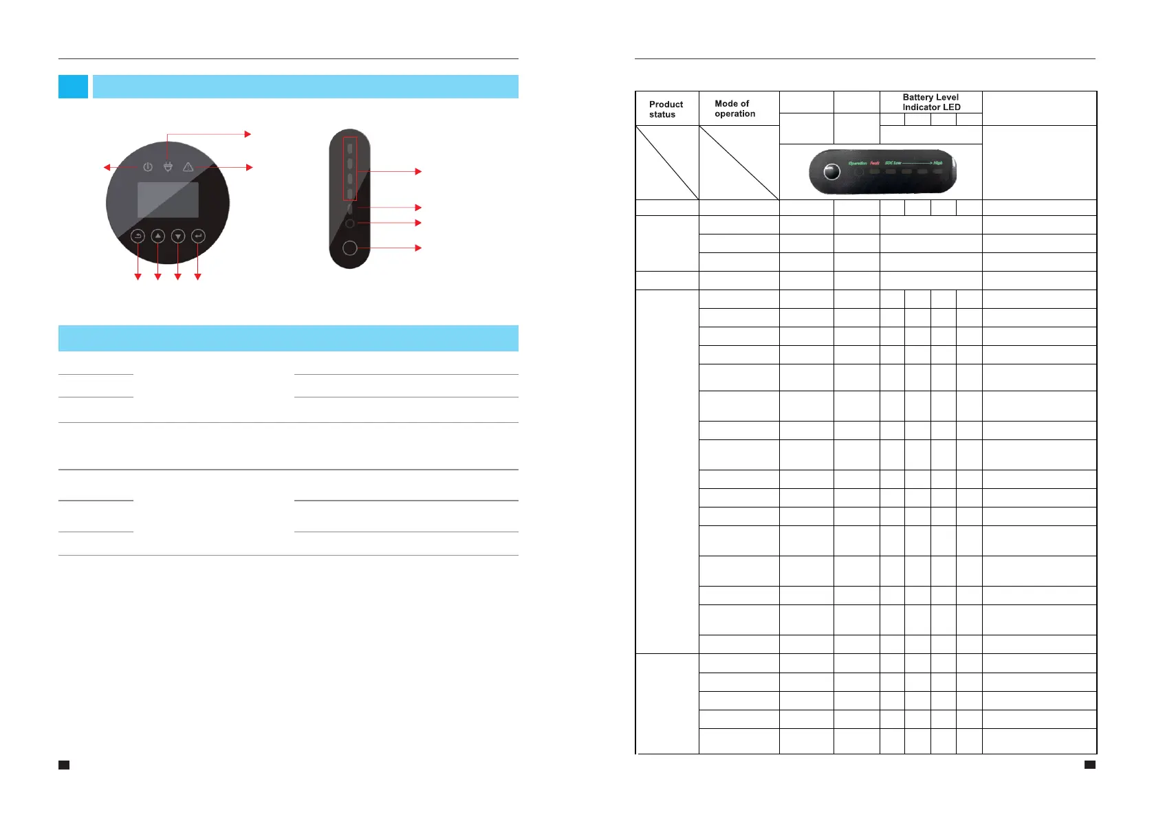
Button Function
Up button: Move cursor to upside or increase
value.
Down Button: Move cursor to downside or
decrease value.
ENT Button: Confirm the selection.
Short Circuit
Protection
Charge protection
Module Over Voltage
Protection
Module Over current
Protection
Module Over voltage
Protection
Module Under voltage
3
3
3
3
3
On
On
On
On
On
On
On
On
On
On
On
On
On
OnOff
Off
Off Off
Off
On
On
On
On
0x340 BYTE 4, 5 BIT6
(Current > 300A)
0x340 BYTE 4, 5 BIT7
(Vmodule > 57.6V,SOC =100%)
0x340 BYTE 4, 5 BIT4 and 5
(Current > 95A)
0x340 BYTE 4, 5 BIT2
(Vmodule > 57.6V)
0x340 BYTE 4, 5 BIT3
(Vmodule < 40.8V)
On On
Protection
EMS Introduction and Set up
04
4.1 Function Description
Figure 29 E8KT/E10KT/E12KT EMS Interface
A
B
C
D E
F
G
Figure 30 PACK Interface
Running light
Fault indicator
Capacity indicator
A
B
C
Indicator LED
Name
Object
Description
Red: The inverter is in fault.
Grid connection
Off-grid
D
Return Button: Escape from current
interface or function.
Enter the setting interface.
Button Function
Reset button
(Start, dormancy
and reset are all
realized by this
Reset button)
LED indicator description