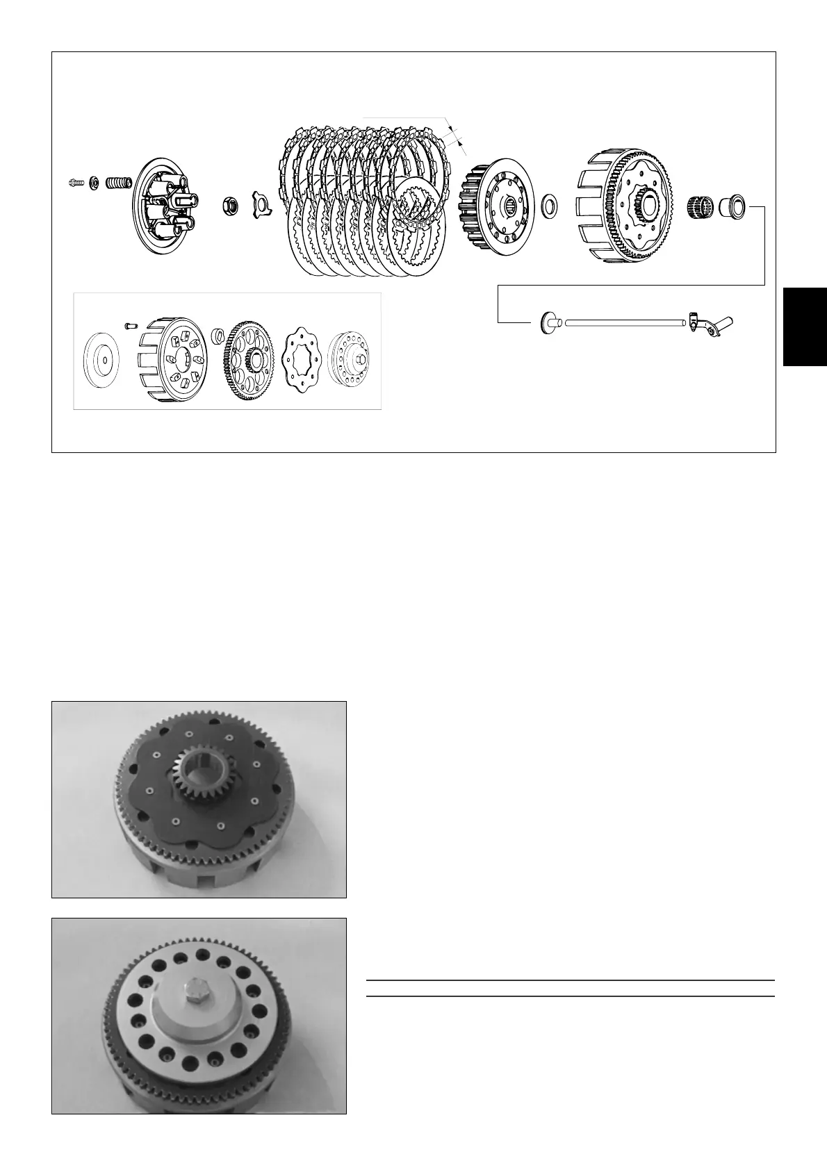
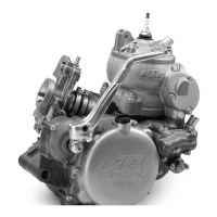
4.16 Clutch
Check the following parts for wear:
THRUST BEARING
1
P
USH ROD
2
C
LUTCH SPRINGS
4
New spring length 43 mm (1.69 in). Used springs may not be more than 1 mm
(0.04 in) shorter than the new ones; replace all 6 springs if applicable.
9 L
INING DISCS
5
Minimum thickness 2.6 mm (0.102 in) / new disc 2.7 mm (0.106 in). Discs must
be plane; there must be minimum spacing of 13.5 mm (0.531 in) between startinq
surfaces.
8 S
TEEL DISCS
6
Must be plane, check for mechanical damage.
I
NNER CLUTCH HUB
9
Check contact surfaces of steel discs on the inner clutch hub, maximum 0.5 mm
(0.02 in) indentations.
P
RESSURE CAP
bk
Check contact surfaces
C
between lining disc and pressure cap for signs of mecha-
nical damage.
O
UTER CLUTCH HUB
bl
Check start surfaces
D
of clutch discs on for wear. If indentations exceed 0.5 mm
(0.02 in), replace outer clutch hub (see below).
Mount inner ring
7
and needle cage
8
and check for clearance.
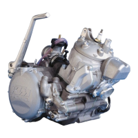
4.17 Replace outer clutch hub
– Drill open the clutch rivets
bm
in area of retaining bracket
bn
and remove parts.
– Check 8 absorbing elements
bo
for signs of mechanical damage, replace all 8
where applicable.
!
CAUTION
!
THE ABSORBING ELEMENTS
bo
ARE WIDER THAN THE PRIMARY GEAR CROWN
bp
. TO ENSURE
THAT THE OUTER CLUTCH HUB
bl
AND RETAINING BRACKET
bn
ARE POSITIONED DIRECTLY ON
THE PRIMARY GEAR CROWN
, THE PARTS MUST BE HELD IN POSITION UNDER TENSION WITH THE
CLUTCH RIVETTING TOOL
bq
WHILE RIVETING.
4
9
min. 13,5 mm