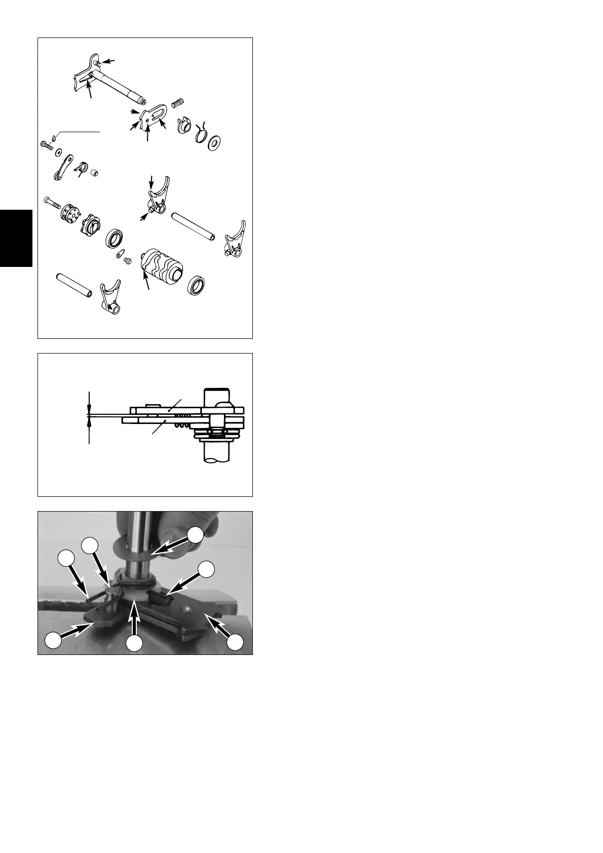
4.18 Shift mechanism
SHIFT FORKS
1
Check shift fork blades
A
and shift roller driving pin
B
for signs of wear.
S
HIFT ROLLER
2
Check shift grooves
C
for wear.
Check position of shift roller in grooved ball bearings
bl
.
S
LIDE PLATE
3
Check slide plate at meshing points
D
for wear.
Check return surface
E
for wear (renew, if strongly notched).
Check that guide pin
G
is securely fixed and check for wear.
S
LIDING GUIDES
F
Check sliding guides (excess between guide pin and shift quadrant not to be more
than 0.7 mm / 0.03 in).
B
ALL BEARINGS
bl
Check ball bearings for easy movement.
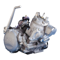
S
HIFT MECHANISM
Assemble shift mechanism (see below) and check free play between slide plate
3
and shift quadrant
4
. Free play should be 0.4 - 0.8 mm (0.016 - 0.032 in).
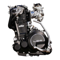
4.19 Preassembly of shift shaft
– Fix shift shaft in vice at shorter end (use covered clamps).
– Mount slidie plate
3
with guide pins downwards, hook guide pins into shift qua-
drant
4
.
– Mount pressure spring
6
.
– Slide on spring guide
7
, slide on return spring
8
with offset end upwards over
the spring guide and lift offset end over bolt
9
(see illustration).
– Mount the stop disc
bk
(14x30x1 mm).
4
0
3
4
6
7
8
9
10