7-3
Measuring static ignition values with peak voltage adapter
Measuring conditions:
– cold engine
–remove starting number plate
– unscrew sparkplug, plug on and hold against ground
– all plug and socket connectors and ground connections in a
non-corroding condition
– depress the kickstarter forcefully at least 5 times for each
measurement
Check the pulse generator for output signal – white/red and white/blue
cables:
– Apply the red measuring tip of the peak voltage adapter to the
white/red cable and the black measuring tip to the white/blue cable,
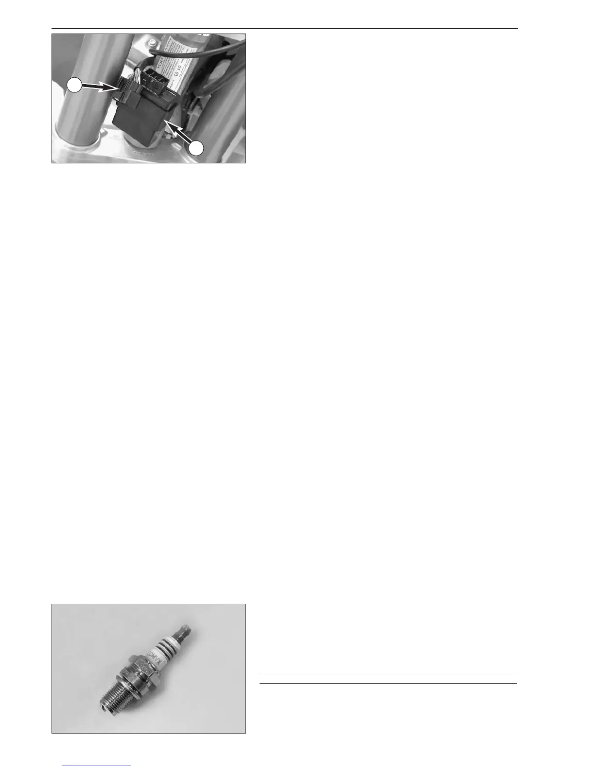
disconnect plug
1 to disconnect the CDI unit 2
Multimeter display: 10 volts +/-1 volt
– Same measurement with CDI unit connected
Multimeter display: 6 volts +/-1 volt
Check the CDI voltage supply for output voltage – green/red and black
cables:
– Apply the red measuring tip of the peak voltage adapter to the
green/red cable and the black measuring tip to the black cable,
disconnect plug
1
Multimeter display: 40 volts +/-5 volts
– Same measurement with CDI unit connected
Multimeter display: 35 volts +/-5 volts
Check capacitor charging coil for output voltage – black/red and
green/white cables:
– Apply the red measuring tip of the peak voltage adapters to the
black/red cable and the black measuring tip to the green/white cable,
disconnect plug
1
Multimeter display: 270 volts +/-20 volts
– Same measurement with CDI unit connected
Multimeter display: 230 volts +/-20 volts
Check the primary voltage output for ignition coil control (orange
cable):
– Apply the red measuring tip of the peak voltage adapter to the
(ground) and the black measuring tip to the orange cable, CDI unit
and ignition coil connected
Multimeter display: 230 volts +/-20 volts
NOTE: If no voltage can be measured during the test, check the
respective cable for continuity before replacing any parts.
Spark plug (NGK BR 10 ECMVX)
– Set the electrode distance.
Electrode distance: 0.60 mm
Insulator
Check for cracks and fissures.
!
CAUTION
!
ALWAYS USE A SPARK PLUG WITH RESISTOR. OTHERWISE PROBLEMS CAN OCCUR IN
THE
CDI UNIT.
2
1


 To Next Page