M-26
WG972-E2, DF972-E2, WSM
GASOLINE / LPG ENGINE
■ Charging Machanism
The charging mechanism is described in four
sections:
1. When key switch is "ON".
2. At starting
3. In charging
4. Over-charge protection
W1034331
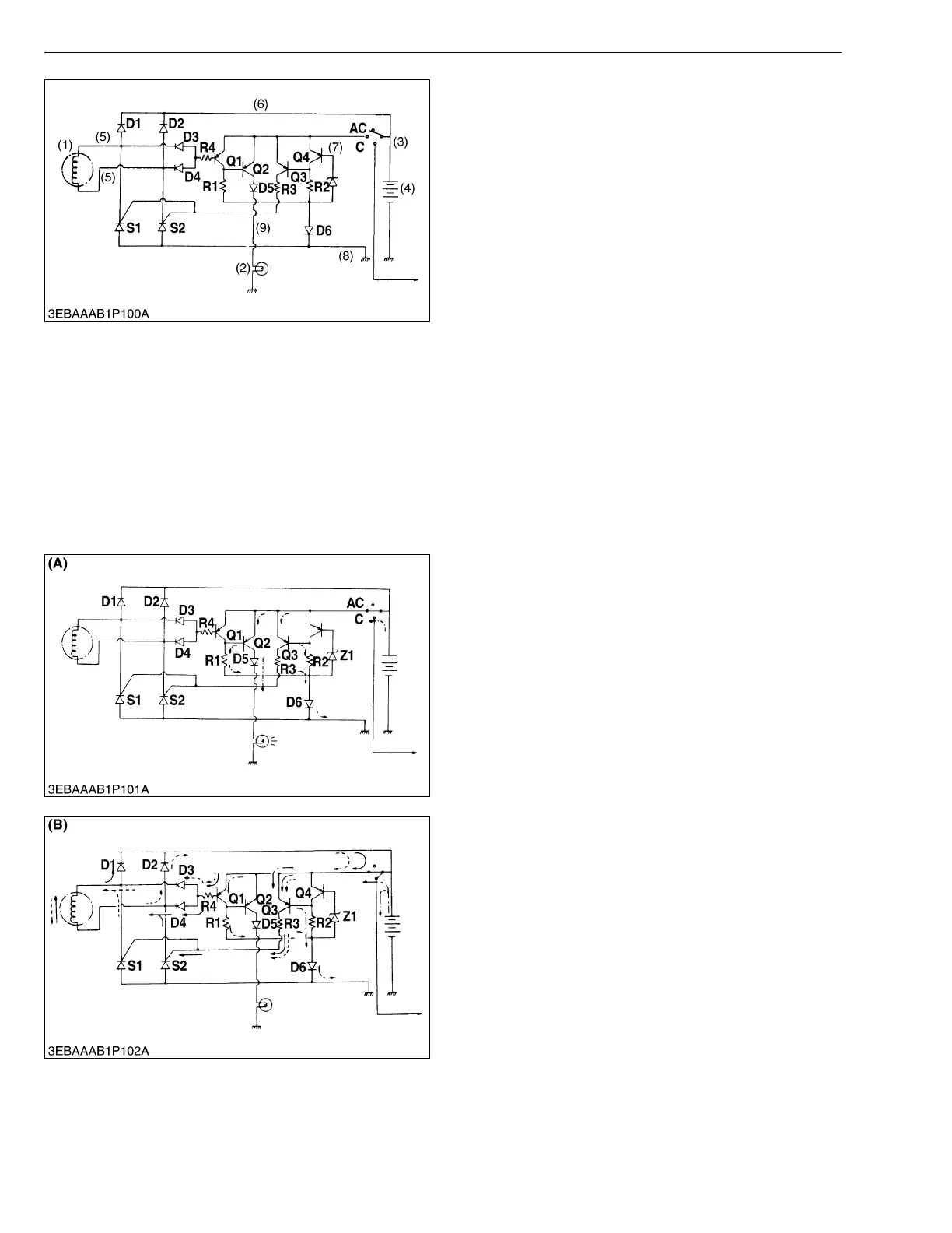
1. When Key Switch is "ON"
When the engine is at standstill with key switch set at
position 1, the circuit functions to light LAMP, as shown
in figure (A). With key switch at position 1, current flows
to base of Q2 through the route of BATT → emitter / base
of Q2 → R1 → D6 → BATT and collector of Q2 is then
turned on. As a result, current also flows to LAMP
though the route of BATT → emitter / collector of Q2 →
D5 → LAMP → BATT lighting LAMP to indicate that
charging is not carried out. At this time, though current
flows to base of Q3 thorugh the route of BATT → emitter
/ base of Q3 → R2 → D6 → BATT, collector of Q3 has no
current because GEN is stationary.
W1035327
2. At Starting
When key switch is turned to position 2, coil of starter
relay is energized and starter starts engine. GEN also
starts generation for charging and LAMP is turned off.
In detail, with GEN starting, current flows to base of
Q1 through the route of GEN → D1 → emitter / base of
Q1 → R4 → D4 → GEN, or GEN → D2 → emitter / base
of Q1 → R4 → D3 → GEN, and therefore current also
flows through Q1, shortcircuiting emitter and base of Q2.
. As a result, base current of Q2 is interrupted, Q2 is
turned off and accordingly current to LAMP is also
interrupted.
W1035571
(1) GEN:
(2) LAMP:
(3) KEY SW:
(4) BATT:
(5) Blue:
(6) Red:
(7) Yellow:
(8) Black:
(9) Green:
S1, S2:
D1, D2:
D3, D4:
D5, D6:
Z1:
Q1:
Q2:
Q3:
Q4:
Magnet type AC generator
Charge indication lamp (not included in the basic
engine)
Key switch
Battery (not included in the basic engine)
GEN connecting terminal
BATT + connecting terminal
BATT voltage test terminal
BATT - connecting terminal
LAMP connecting terminal
Output control / rectification thyristor (SCR)
Output rectifying diode
GEN generation detecting diode
Protection diode for wrong connecting of BATT
BATT terminal voltage setting diode
GEN generation detecting transistor
LAMP on / off transistor
Gate current control transistor
BATT voltage detecting transistor