S-44
V3300-E2B, V3300-T-E2B, WSM
DIESEL ENGINE
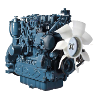
Installing Procedure (Continued)
1. Move the stop lever (1) and visually check to see if the fuel
injection pump control rack comes smoothly back to the start
position by the counter force of the start spring.
2. If the control rack fails to move back smoothly, remove the start
spring and the anti-rotation nut, take the above steps from 2 of
the former page again.
3. Finally fit the sight cover and the stop solenoid back into place.
W1069772
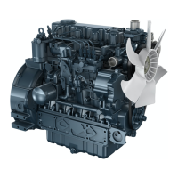
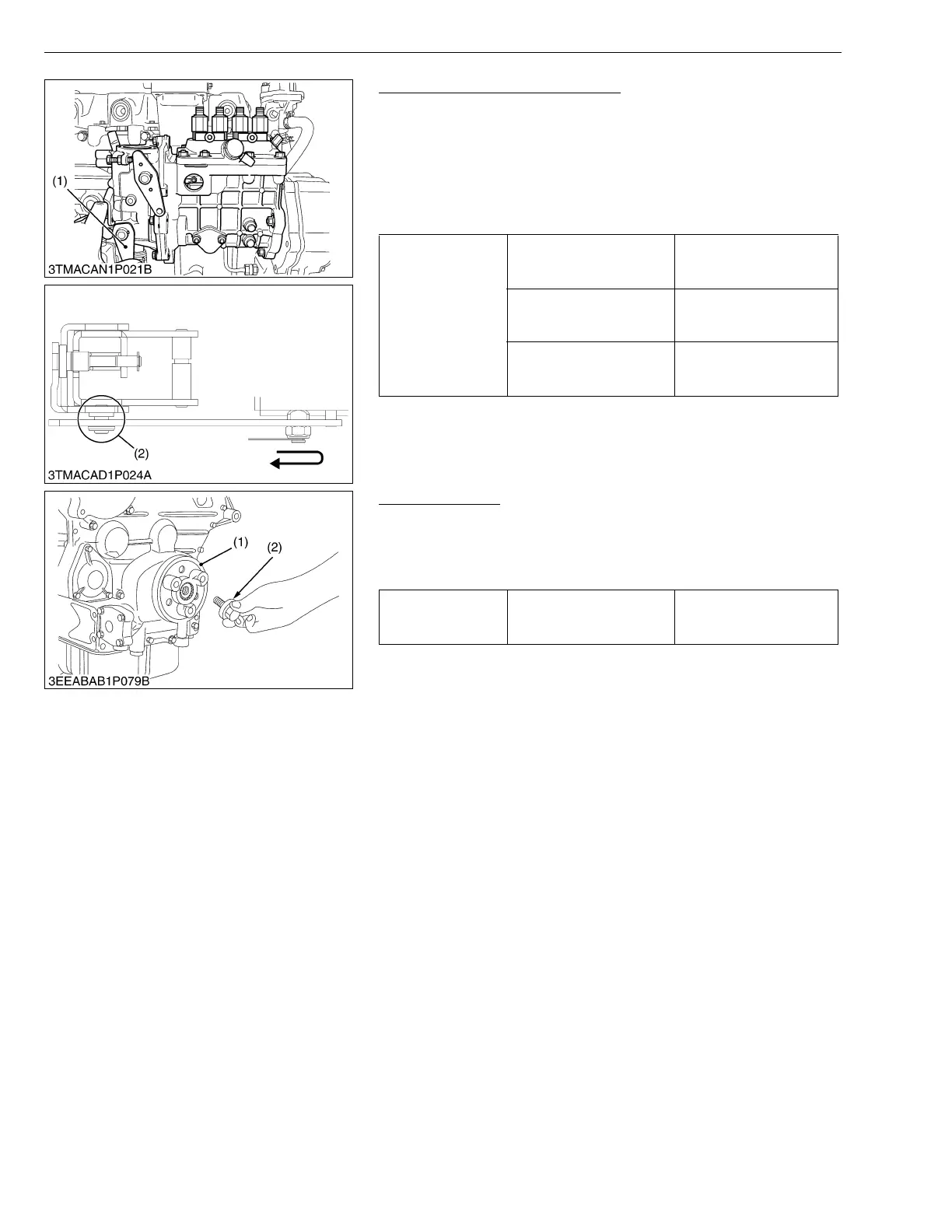
Fan Drive Pulley
1. Set the stopper to the flywheel.
2. Remove the crankshaft screw (2).
3. Draw out the fan drive pulley (1).
(When reassembling)
W1185033
Tightening torque
Anti-rotation nut
2.8 to 4.0 N·m
0.29 to 0.41 kgf·m
2.1 to 3.0 ft-lbs
Injection pump mounting
screw
23.5 to 27.5 N·m
2.4 to 2.8 kgf·m
17.4 to 20.3 ft-lbs
Injection pump mounting
nut
17.7 to 20.6 N·m
1.8 to 2.1 kgf·m
13.0 to 15.2 ft-lbs
(1) Stop Lever (2) Sliding Point between Governor Fork
Lever and Governor Connecting Rod
Tightening torque Crankshaft screw
255.0 to 274.6 N·m
26.0 to 28.0 kgf·m
188.1 to 202.5 ft-lbs
(1) Fan Drive Pulley (2) Crankshaft Screw