54-0274-01 Rev. A 8 © 2005 KVH Industries, Inc., All rights reserved.
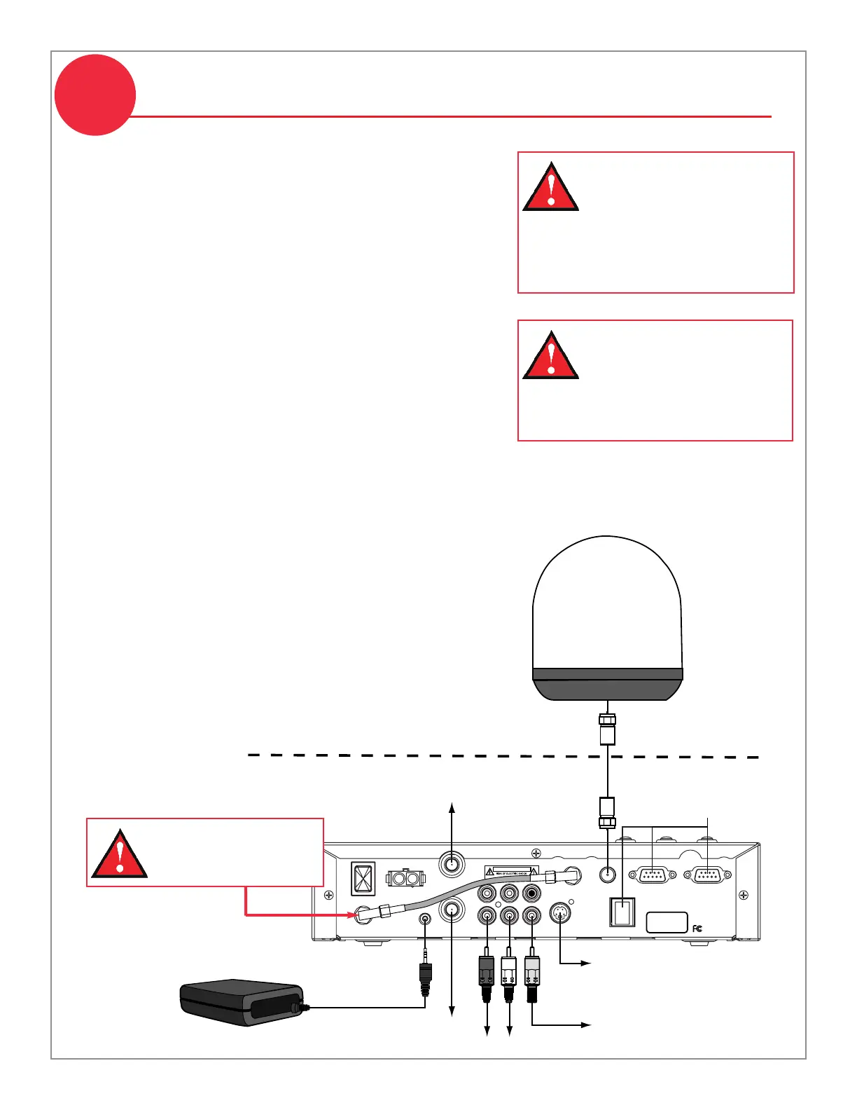
1. Connect the antenna cable (A) to the “To KVH
Antenna” jack. Do not kink/stress the cable.
2. Connect the RF converter cable (B) to the “RF
Remote Input” jack.
3. Connect the receiver to the vessel’s entertainment
system (TV). Choose one of the following options:
Option 1 - RCA-type A/V jacks (use bottom row)
Option 2 - S-Video jack (provides best picture quality)
Option 3 - RF coaxial connector
Cables for option 1 are included in the kit.
4. (Optional) If you have a VHF TV antenna onboard,
you can connect it to the “VHF Antenna In” jack on
the receiver. If you connect a VHF antenna to the
receiver, you need to use the receiver’s RF coaxial
connector (option 3) to supply VHF video to the TV.
5. Be sure to tighten all connections. Also be sure to
leave enough slack in the cables (service loop) for
easy serviceability, allowing you to access the
receiver’s rear panel with the cables connected.
For details on connecting an additional receiver,
please see Appendix A in the Receiver User’s Guide.
Wire the Receiver
7
Do not shorten or extend
the antenna cable. Since the
antenna cable carries data,
power, and communications,
the integrity of this cable
and its connections is very
important.
Antenna
RF Converter
Receiver
Deck
Service/
Maintenance
Only
To Audio
To Video
(Option 1)
To Video
(Option 1)
To Video
(Option 3)
To Video
(Option 2)
To VHF Antenna
(Optional)
POWER
VEHICLE POWER
(10-16 VDC)
VHF ANTENNA
IN
AUDIO R AUDIO L VIDEO
S – VIDEO
PHONE JACK
RF
REMOTE
INPUT
OUT TO TV
TUNER
SATELLITE IN
CAUTION
This device complies with Part 15 of the FCC rules. Operation is subject
to the following two conditions: (1) This device must not cause harmful
interference, and (2) This device must accept any interference received,
including interference that may cause undesired operation.
Tested to comply
with FCC Standards
TO SATELLITE
IN
TO KVH
ANTENNA
DIAGNOSTICS
PORT 1
DIAGNOSTICS
PORT 2
(A)
(B)
 Loading...


