EN
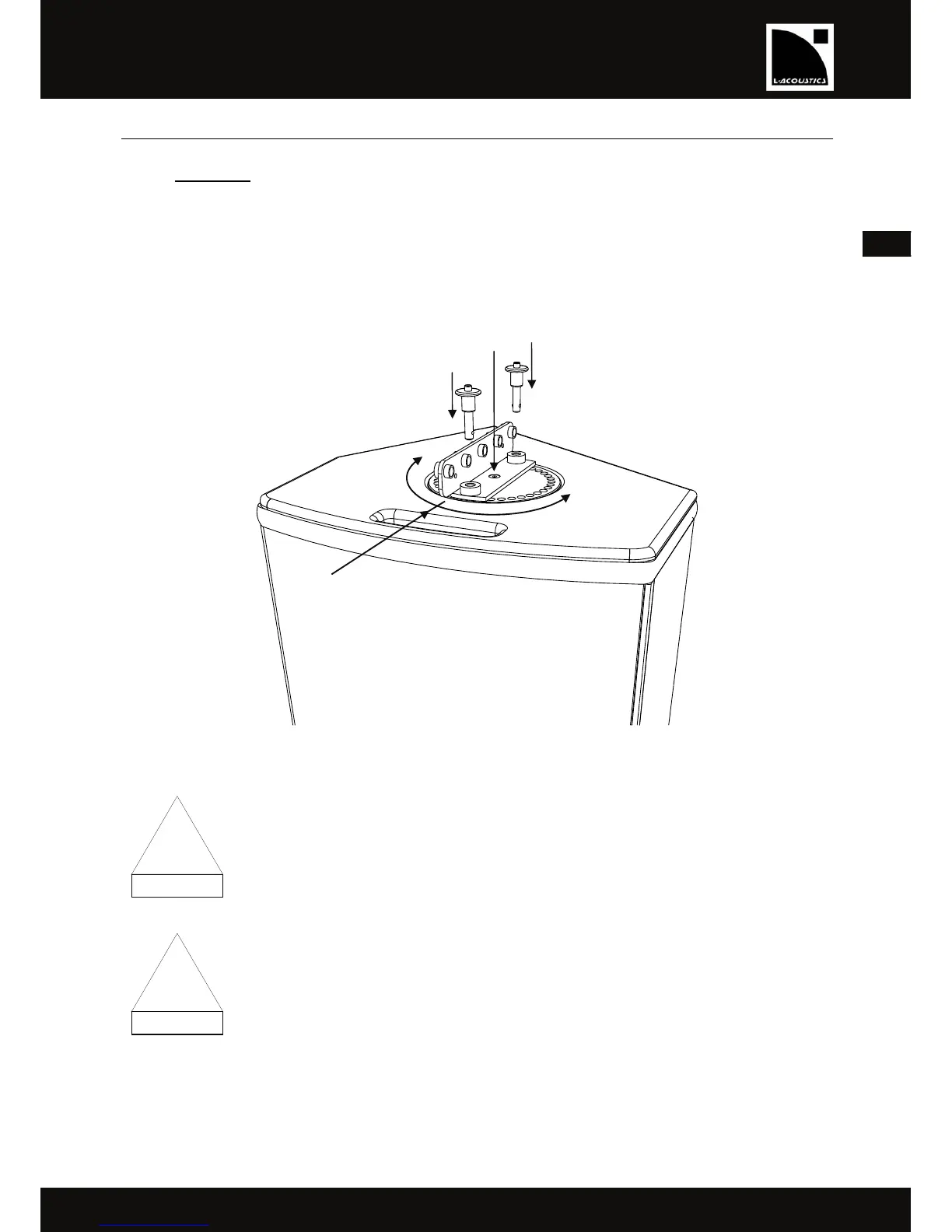
6.4 Flying the 12XT, 112P, or 115XT HiQ enclosure with the XTLIFTBAR
6.4.1 Assembling
1. Remove both locking pins.
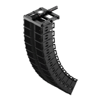
2. a. Insert the XTLIFTBAR stud into the enclosure’s top pole socket.
b. Select the desired angle: in 10° steps for azimuth angle setting (directivity in the horizontal plane), or at the 0°
position (parallel to the sides of the enclosure) for site angle setting (directivity in the vertical plane).
c. Engage both locking pins to secure the XTLIFTBAR to the enclosure.
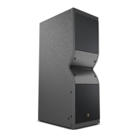
Figure 17: XTLIFTBAR secured to the enclosure for setting site angle
Verify that the enclosure is correctly secured to the XTLIFTBAR
by checking that both locking pins are engaged and cannot move freely.
For site angle setting, ensure that the XTLIFTBAR is parallel to the enclosure’s sides
in order to properly balance the center of gravity.
0° position
a.
c.
c.
b. Setting the
angle in 10° steps
!
 Loading...