L-ACOUSTICS P Series Manual V2.1 7/12/2007 5
LIST OF FIGURES
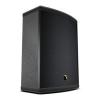
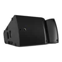
Figure 1: 108P, 112P Loudspeaker Enclosures……………………………………………………………… 6
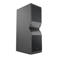
Figure 2: SB15P self-powered subwoofer…………………………………………………………………... 7
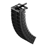
Figure 3: P Series Rigging Components……………………………………………………………………… 8
Figure 4: 108P Enclosure ……………………………………………………………………………………. 9
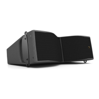
Figure 5: 112P Enclosure……………………………………………………………………………………. 10
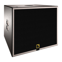
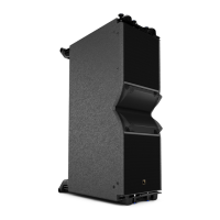
Figure 6: SB15P Enclosure…………………………………………………………………………………... 11
Figure 7: 108P, 112P preset selector switch closeup and preset options………………………………….. 12
Figure 8: SB15P preset selector switch closeup…………………………………………………………….. 13
Figure 9: SB15P with positive polarity, 108P or 112P in X-OVER mode ………………………………….. 13
Figure 10: SB15P with negative polarity, 108P or 112P in FRONT mode ………………………………… 13
Figure 11: 108P (floor monitor orientation)………………………………………………………………... 14
Figure 12: 112P (floor monitor orientation)………………………………………………………………... 15
Figure 13: SB15P (with pole-mounted 108P )……………………………………………………………… 17
Figure 14a: 108P / 112P DSP Power Amplifier Module Rear Panel………………………………………... 18
Figure 14b: SB15P DSP Power Amplifier Module Rear Panel……………………………………………… 18
Figure 15: P Series mains power cables…………………………………………………………………….. 18
Figure 16: Daisy-chain connection of P Series enclosures………………………………………………….. 19
Figure 17: Connecting unbalanced sources…………………………………………………………………. 19
Figure 18: General guidelines for aiming P Series enclosures………………………………………………. 20
Figure 19: General guidelines for 108P or 112P enclosure spacing………………………………………… 21
Figure 20: ETR8-2 U-bracket installation procedure……………………………………………………….. 23
Figure 21: ETR112XT U-bracket installation procedure………………………………………………….... 25
Figure 22: XTLIFTBAR installation procedure………………………………………………………..……… 25
Figure 23: ETR15P U-bracket installation procedure…………………………………………….……… 26
Figure 24: 108P Line Drawing………………………………………………………………………….……. 30
Figure 25: 108P + ETR8-2 Line Drawing……………………………………………………………………. 31
Figure 26: 112P Line Drawing……………………………………………………………………………….. 32
Figure 27: 112P + ETR112XT Line Drawing………………………………………………………………... 34
Figure 28: 112P + XTLIFTBAR Line Drawing………………………………………………………………. 35
Figure 29: SB15P Line Drawing………………………………………………………………………………. 37
Figure 30: SB15P + ETR15P Line Drawing………………………………………………………………. 38