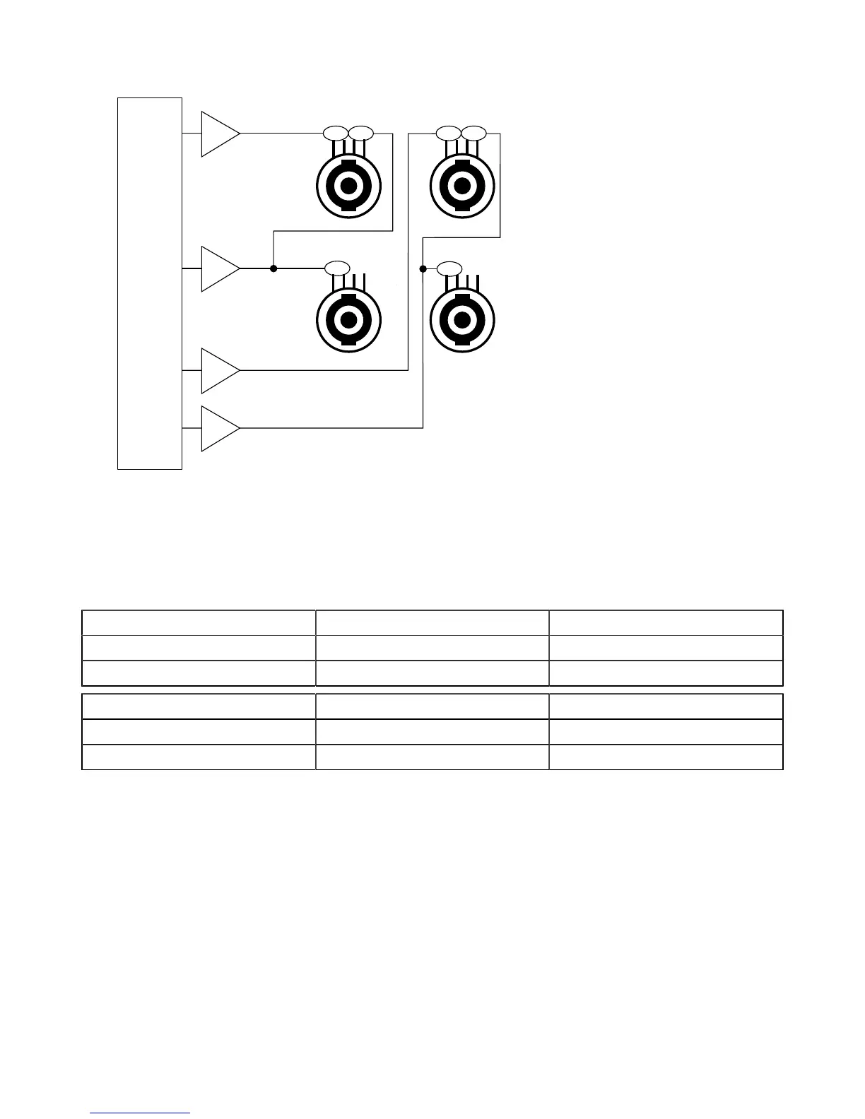
Installation
Output audio paths
1+ 1- 2+ 2-
1+ 1- 2+ 2-
top left
bottom left
DSP
1+ 1- 2+ 2-
top right
1+ 1- 2+ 2-
bottom right
OUT 1
OUT 2
OUT 3
OUT 4
Signal panels
The eight XLR connectors on the rear panel are for analog or digital signal cabling.
The XLR connectors can transport analog or digital signals depending on the input mode selected by the user for channel
pairs AB and CD (the two selections can be different). Connections to the IN connectors are referenced in the table. Refer
also to section INPUT MODE (p.41).
Input mode AB IN A / IN A&B IN B
Analog analog audio source (1 channel) analog audio source (1 channel)
AES/EBU digital audio source (2 channels) not used
Input mode CD IN C / IN C&D IN D
Analog analog audio source (1 channel) analog audio source (1 channel)
AES/EBU digital audio source (2 channels) not used
Each LINK connector is wired to the corresponding IN connector, and thus transports the same type of signal.
19 LA4X user manual (EN) version 9.1
 Loading...