20 PDX3000 Quick Start Guide 21
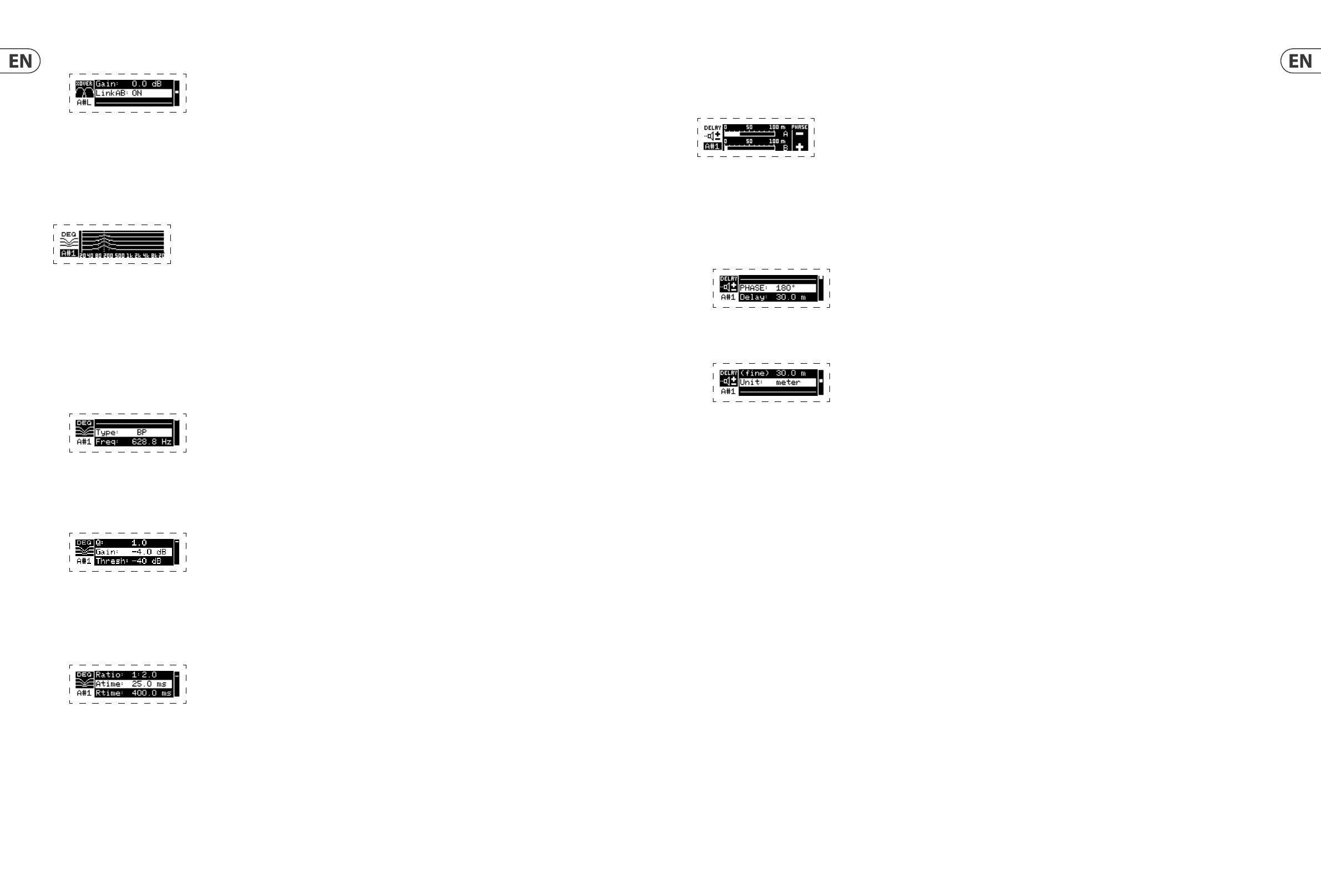
4.4.5 DELAY
The DELAY DSP module digitally slows the nal signal output from the ampli er by a programmable amount (expressed as either distance or time). This signal delay helps
prevent phase and synchronization problems caused by sound traveling through air over long distances, e.g., between speaker arrays separated by long distances or between
a performance stage and distant sound reinforcement speakers.
Programming signal delay
1. Choose between signal paths (A#1, B#1) by rotating the SELECT encoder knob.
2. Press the SELECT encoder knob to enter the parameter screens.
3. Move up or down between parameters by pressing the UP / DOWN arrow buttons.
4. Choose between 0° and 180° phase (PHASE) by rotating the SELECT encoder knob.
5. Choose your amount of signal delay (Delay) by rotating the SELECT encoder button.
6. Fine tune the Delay value using the (fine) parameter.
7. Change the delay’s unit of measure (Unit), if necessary, by rotating the SELECT encoder knob. The delay value can be expressed in milliseconds (ms), meters (m),
or feet (ft).
8. Press the SELECT encoder when finished to return to the top-level DELAY screen.
4.4.6 LIMIT
The LIMIT DSP module controls the unit’s output limiter, with programmable parameters for threshold (Thresh), release (Rtime), and hold (Hold).
The top-level LIMIT screen always displays the threshold (Thresh) setting for quick reference.
Programming the output limiter
1. Choose between signal paths (A#1, B#1) by rotating the SELECT encoder knob.
2. Press the SELECT encoder knob to enter the parameter screens.
3. Move up or down between parameters by pressing the UP / DOWN arrow buttons.
4. Choose a threshold (Thres) setting by rotating the SELECT encoder knob.
5. Choose a release time (Rtime) by rotating the SELECT encoder knob.
6. Choose a hold (Hold) setting by rotating the SELECT encoder knob.
7. Press the SELECT encoder when finished to return to the top-level LIMIT screen.
6. Set the filter’s overall signal gain (Gain) by rotating the SELECT encoder knob.
7. Set the link parameter (LinkAB) to ON or OFF by rotating the SELECT encoder knob (BIAMP1 and BIAMP2 modes only).
8. Press the SELECT encoder when
finished to return to the top-level XOVER screen.
4.4.4 DEQ
The DEQ module deploys a dynamic EQ that is triggered by a programmable signal thresold. For example, you can program the dynamic EQ to cut or boost increasing
amounts of mid frequencies as the signal gets louder beyond your preferred threshold.
STEREO mode features one set of dynamic EQs (A#1 and A#2), while DUAL, BIAMP1, and BIAMP2 modes feature two sets of dynamic EQs (A#1, A#2, B#1, and B#2). Each
dynamic EQ may be set to OFF, band-pass (BP), low-pass (LP6, LP12), and high-pass (HP6, HP12).
Programming dynamic EQs
1. Choose between dynamic EQ sets by rotating the SELECT encoder knob.
2. Press the SELECT encoder knob to enter the parameter screens.
3. Move up or down between parameters by pressing the UP / DOWN arrow buttons.
4. Choose between EQ types (Type) by rotating the SELECT encoder knob.
5. Set the frequency (Freq) for each EQ by rotating the SELECT encoder knob. The programmed frequency can represent either the center frequency for band-pass
mode, or the threshold frequency for low- and high-pass modes.
6. For band-pass mode, control the width of the band-pass curve by tweaking the Q parameter. High Q values produce a narrow, steep curve, while low Q values
create a wide curve with a gentle slope.
7. Set the dynamic equalizer’s cut or boost (Gain) by rotating the SELECT encoder knob.
8. Set the signal threshold (Thresh) by rotating the SELECT encoder knob.
9. Program your desired ratio (Ratio). Similar to a compressor, higher ratio values yield a more intense equalization effect.
10. Adjust attack (Atime) and release (Rtime) to your preferred values.
11. Press the SELECT encoder when finished to return to the top-level DEQ screen.

 Loading...