12 PDX3000 Quick Start Guide 13
3. DSP Configuration
3.1 Default configuration
PDX Series ampli ers are shipped with default DSP settings that allow immediate use in many common applications with no need for further DSP con guration.
The default mode is suited for use with stereo program material into fullrange loudspeakers.
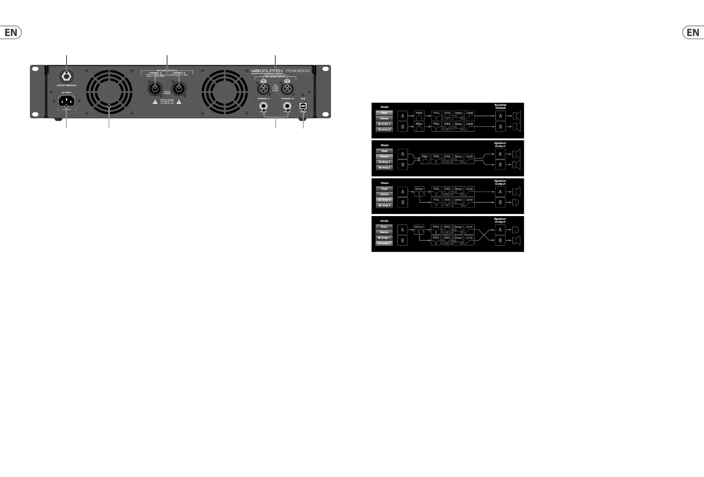
3.2 Signal flow block diagram
The block diagrams below (Fig. 3) show the available signal- ow con gurations from inputs to outputs.
Fig. 3: Available Signal-Flow Con gurations
All of these con gurations are available through both the Front Panel interface (see pg. 14) and the PDX Controller software (see pg. 22).
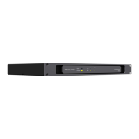
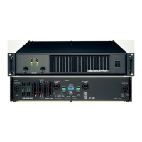
2.2 Rear Panel
The following connectors are available on the rear panel (Fig. 2):
Fig. 2: PDX3000 Rear Panel
(12) BREAKER (automated fuse) acts in place of common discardable fuses. After eliminating the cause of faulty operation, simply depress the BREAKER and power
up the unit again.
BREAKER WARNING: Take the following actions BEFORE resetting the breaker:
• Unplug the AC main cable
• Press the POWER button to the extended “OFF” position
• Turn all input gain control elements down
• And then, reset the breaker, connect the unit to the mains, switch ON and slowly increase the gain to the target volume.
(13) POWER SOURCE locking connector accepts the included IEC power cord.
(14) VENTILATION FAN speed adjusts automatically depending on temperature to ensure trouble-free operation.
(15) SPEAKER OUTPUTS connect the amplifier to the speakers using professional speaker cables with twist-locking speakON plugs. Both output channels are
available by using a 4-pole connector and cable with the CHANNEL A output. CHANNEL B is available separately on the right-hand CHANNEL B output.
WARNING! Bridge Mode is not supported!
WARNING! Do not connect any output connec tor poles to ground!
(16) BALANCED INPUTS (¼ " connec tions) accept audio inputs for each channel from audio cables with ¼ " TRS connectors (balanced) or
¼ " TS connectors (unbalanced).
(17) BALANCED INPUTS (XLR connec tions) accept balanced audio inputs for each channel from audio cables with XLR connectors.
NOTE: The XLR and ¼ " connections in the BALANCED INPUTS section are physically linked, and users can use this physical connection to route a copy of the input
signal to an additional amplifier. For example, a signal coming in to Channel A through the XLR connection can be split and routed back out over Channel A’s
¼ " TRS connection.
(18) USB connection enables firmware updates and control over parameters via computer. Please visit labgruppen.com to download the PDX Controller software
for your computer.

 Loading...