Chapter 3: Getting Started
Product Service 816-333-8811 or 1-800-522-7658
11
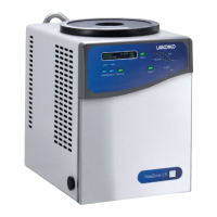
Electrical Connection
Plug the power cord into the receptacle on the back of the freeze dryer and
plug the other end into a suitable power receptacle.
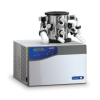
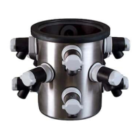
Drying Chamber or Drying Manifold Installation
Install the clear lid with 3.0 inch hole on top of the collector chamber.
The supplied drying chamber or drying manifold, which may be purchased
separately, may be positioned directly above the 3-inch hole in the collector
chamber lid. Center the rubber gasket that came with the chamber over the
hole in the lid. Then place the chamber over the gasket. When vacuum is
applied to the system, the chamber will be held securely in place.
Chemical Resistance of Freeze Dryer
Components
The FreeZone Freeze Dry System is designed to be chemically resistant to
most compounds that are commonly used in freeze drying processes.
However, by necessity, the freeze dryer is comprised of a number of different
materials, some of which may be attacked and degraded by certain chemicals.
The degree of degradation is dependent on the concentration and exposure
duration. Some of the major components of the FreeZone Freeze Dry System
that are susceptible to degradation are as follows:
Acids Buffers Solvents
Component Material
Acetic Acid 20%
Formic Acid
Trifluoroacetic Acid (TFA)
Calcium Chloride
Sodium Phosphate
Acetone
Acetonittirle
Carbon Tetrochloride
Cyclohexane
Dioxane
Methyl t-Butyl Ether (BTBE)
Pyridine
Valve Stem Acetal (Delrin) C D D D D
Collector Lid Acrylic D D D D
Hoses, Gaskets
& Valve
Bodies
Neoprene C D D C C D D D C D
Flask Top Silicon Rubber C D D D D D C D
Chamber &
Fittings
Stainless Steel C