- 30 -
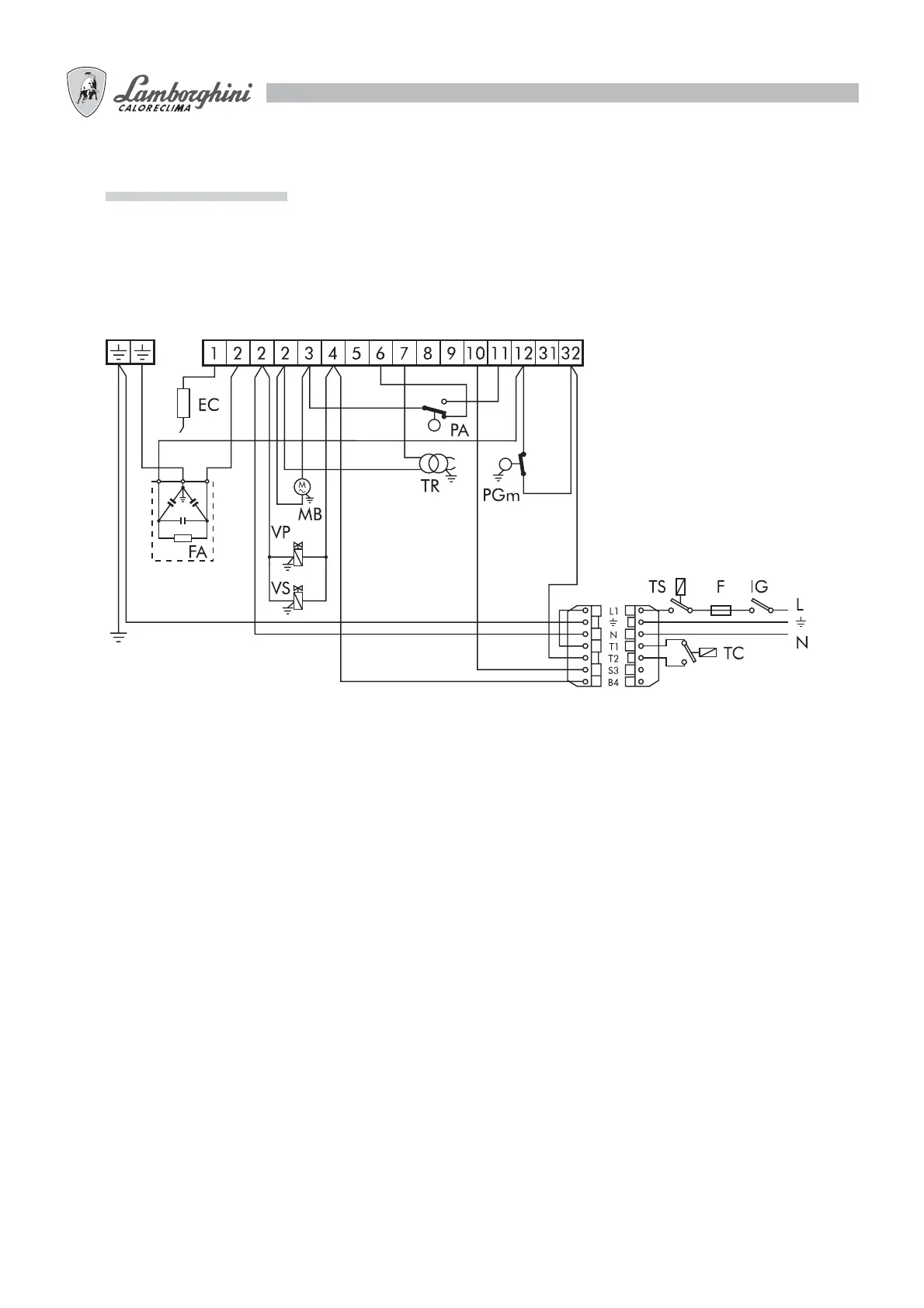
WIRING DIAGRAMS
The connections to be carried out by the installer are:
- Main supply line
- Thermostatic line
- Lock-out lamp at terminal S3 (if present)
- Hour counter at terminal B4 (if present)
MPE
Mains supply
230V-50Hz
Legend
EC Control electrode
F Fuse
FA Anti-interference filter
IG Main switch
MB Burner motor
MPE Control box terminal board
PA Air pressure switch
PGm Minimum gas pressure switch
TC Boiler thermostat
TR Ignition transformer
TS Safety thermostat
VP Main valve
VS Safety valve
NOTE: Always make sure that no more than two wires are connected to each terminal.
Warning:
- Do not invert the neutral with the phase.
- Make the connection to an efficient earthing system.
- The electrical power line to the burner must be fitted with an omnipolar switch with an opening of at least 3 mm between
the contacts.
- The earth connection to the terminal board of the burner must be made with a cable at least 20 mm longer than the phase
and neutral cables.
- Must be workmanlike performed and comply with the regulations in force.