A
Amanda BrooksAug 4, 2025
What to do if LaMotte Measuring Instruments displays 'BAT'?
- Cconnie11Aug 4, 2025
If your LaMotte Measuring Instruments device is displaying 'BAT', this indicates a low battery. You should change the battery.
What to do if LaMotte Measuring Instruments displays 'BAT'?
If your LaMotte Measuring Instruments device is displaying 'BAT', this indicates a low battery. You should change the battery.
How to troubleshoot suspect calibration in LaMotte Measuring Instruments?
If you suspect the calibration of your LaMotte Measuring Instruments is off, here are a few things to check: * Use new standards to check the calibration. * Run an alternate test with Formazin to verify the standards. * Check the calibrations against another meter. * Re-align the tube. * Inspect the sample tubes for dirt and scratches; clean or replace them if needed. * Ensure internal meter components are dry, always drying tubes before inserting and checking for visible moisture.
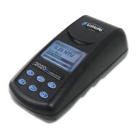
Why won't my LaMotte 2020 turn on?
If your LaMotte Measuring Instruments device isn't turning on, the issue might be with the power source. First, try replacing the battery. If that doesn't work, ensure the AC adapter is properly plugged in and that the AC wall outlet is providing power.
What to do if LaMotte 2020 Measuring Instruments shows error 'er2'?
If your LaMotte Measuring Instruments device is showing 'er2', it indicates an over range condition. Dilute the sample to resolve this.
What causes 'er3' error on LaMotte 2020?
If your LaMotte Measuring Instruments device is displaying 'er3', it could be due to a burnt-out bulb or a misaligned tube. Check the tube alignment.
Information on packaging, delivery, and returning instruments for service or repair.
Important safety guidelines and warnings for operating and storing the instrument.
Details on handling reagents, MSDS, and emergency information.
Disclaimer regarding the manufacturer's liability for product misuse.
Defines the instrument as a Nephelometric turbidity meter calibrated in NTU.
Specifies the operational range of the instrument from 0.00 to 1100 NTU.
Details the accuracy specifications for readings below and above 100 NTU.
Outlines the resolution for Standard and EPA modes across different NTU ranges.
States the display type as 3½ digits.
Indicates the time taken for the instrument to provide a reading.
States that no warm-up time is required before operation.
Specifies the duration before the meter automatically shuts off.
Identifies the light source as a Tungsten Filament bulb with an 800-hour life.
Defines the sample volume and type (15 mL in capped tube).
Describes the type of tubes the sample chamber accepts.
Lists the available power sources: battery and AC adapter.
Provides the physical dimensions of the meter in cm and inches.
Gives the weight of the meter and the kit.
Details the serial interface type and configuration.
Lists the items that come standard with the meter kit.
Lists additional accessories available for purchase separately.
Indicates the instrument meets or exceeds EPA specifications for turbidity monitoring.
Details the one-year limited warranty on material and workmanship.
Formal declaration that the equipment meets specified EU directives and standards.
Defines turbidity, its causes like suspended matter, and its importance in different applications.
Explains how turbidity is measured by detecting scattered light.
Discusses various measurement methods including visual and instrumental techniques.
Illustrates the internal components and optical path of the 2020 Nephelometer.
Details the historical Jackson Candle method and contrasts it with nephelometry.
Explains the working principle of nephelometers like the 2020, measuring scattered light.
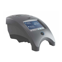
Introduces the 2020 Turbidimeter as a portable, microprocessor-controlled nephelometer.
Details its optical configuration, signal averaging, auto-ranging, keypad, and power options.
Explains the connectivity options for data acquisition and printing via RS-232.
Diagram showing the back view of the instrument with ports.
Diagram showing the side view of the instrument, highlighting the lid and AC socket.
Diagram showing the top view of the instrument, including the display and buttons.
Diagram showing the bottom view, indicating the serial number and battery compartment.
Details how the display shows readings, resolutions, and software version.
Explains the sequence of operations and display messages for the READ button.
Describes the display indicator during measurement.
Explains the display behavior during the calibration adjustment.
Describes the process for turning the meter off using the READ button.
Lists error codes ("E-1", "Er2", "Er3", "BAT") and their meanings.
Explains the function of the UP/DOWN arrow buttons during calibration.
Details the function of the READ button for power and measurement.
Details the function of the CAL button for calibration and mode switching.
Instructions for washing, drying, and handling turbidity tubes to ensure accurate readings.
Emphasizes care in handling to prevent scratches, fingerprints, and ensure cleanliness.
Explains how glassware quality affects results and the importance of aligning the tube index mark.
Discusses potential variations in tubes and the importance of individual calibration for low NTU samples.
Step 1: Prepare sample tube with high-quality water.
Step 2: Record initial turbidity readings for each tube.
Step 3: Mark the reference tube with an 'R'.
Step 4: Use calibration standards and procedure on page 16.
Step 5: Fill remaining tubes with the same calibration standard.
Step 6: Insert tubes into the meter and record readings.
Step 7: Calculate correction factors for individual tubes.
Information on the pre-calibration of the 2020 and the use of AMCO standards.
Explains factory pre-calibration and user standardization for narrow ranges.
Describes supplied AMCO standards and precautions for their use and storage.
Step 1: Select appropriate standard for testing range.
Step 2: Prepare sample tube with standard and wipe clean.
Step 3: Align tube index mark and insert into chamber.
Step 4: Take initial reading and check against standard.
Step 5: Initiate calibration adjustment with CAL and arrow buttons.
Step 6: Save calibration by pressing CAL again.
Step 7: Turn off meter or proceed to measurements.
Important note about calibration frequency and independence from operating mode.
Instructions on how to switch between standard and EPA operating modes.
Explains the two operating modes and how to switch them.
Provides a step-by-step guide to changing operating modes.
Describes how to identify the active mode and what the display shows.
Differentiates between standard and EPA modes regarding displayed resolution.
Reiterates that meter calibration is independent of the operating mode.
Step 1: Prepare sample by collecting and allowing it to equilibrate.
Step 2: Rinse the sample tube with a portion of the sample.
Step 3: Fill the tube with the sample, avoiding bubbles.
Step 4: Cap and dry the sample tube.
Step 5: Align the tube and insert it into the meter.
Step 6: Close lid and take the reading.
Step 7: Manual or automatic meter shutdown procedure.
Advice for handling samples with high turbidity (>1100 NTU).
Mentions an accessory package for preparing turbidity-free water.
Explains the need for careful technique and the use of a filtering device.
Indicates that detailed procedure steps are on the following page.
Step 1: Assemble filter holder with membrane filter.
Step 2: Attach filter holder to the syringe.
Step 3: Force deionized water through the filter.
Step 4: Remove filter holder to prevent membrane damage.
Step 5: Repeat steps to collect desired amount of filtered water.
Advice on filter examination and storage.
Explains the process and limitations of diluting high turbidity samples.
Tip 1: Use clean containers for sample collection.
Tip 2: Analyze samples promptly after collection.
Tip 3: Avoid using scratched turbidity tubes.
Tip 4: Mix samples gently to avoid introducing air bubbles.
Tip 5: Be aware of interference from electric fields.
Tip 6: Note that carbon can cause low readings.
Tip 7: Follow storage and shelf-life guidelines for standards.
Tip 8: Ensure the meter is on a vibration-free surface.
Tip 9: Consider the effect of sample color on readings.
Troubleshooting steps for when the meter fails to power on.
Troubleshooting steps for potential calibration issues.
Action for "Er1" error code (very low battery).
Action for "Er2" error code (over range).
Action for "Er3" error code (bulb or tube issue).
Action for "BAT" indicator (low battery).
Describes how to connect the turbidimeter to a computer or printer via RS232.
Specifies the serial output parameters (baud rate, parity, data bits, stop bit).
Details the physical connection type for computer interface.
Lists the pin assignments for the RS232 port.
Step-by-step guide for replacing the 9-volt battery.
Describes the battery type and compartment location.
Step 1 for battery replacement.
Step 2 for battery replacement.
Step 3 for battery replacement.
Step 4 for battery replacement.
Information on lamp life and when to contact the company for replacement.
Details the lamp's lifespan and troubleshooting guidance.
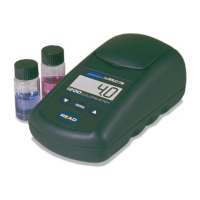
| Type | Colorimeter |
|---|---|
| Parameter | Bromine |
| Measurement Range | Varies by parameter. Refer to manual. |
| Resolution | Varies by parameter. Refer to manual. |
| Accuracy | Varies by parameter. Refer to manual. |
| Power Supply | Battery |