Page 14PROTECTOR® IV Top of Rail Installation, Operation & Maintenance Manual
Start Up
The following sections explain how to ensure the unit is functioning properly, setup the unit and how to use
and control the various options. These options are controlled from the DCB.
When supplied with a PROTECTOR IV unit the leads are disconnected from the battery for transport purposes,
ensure that these are re-connected. Red or brown wires are connected to the positive battery terminal, black
or blue wires connect to the negative terminal.
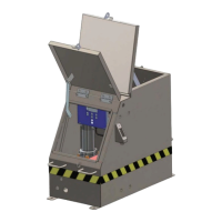
Charge Controller (DC units only)
The solar panel charge controller is situated inside the clean hand compartment. There are three LED lights on
the charge controller labeled: Charge, Low and High that refer to the battery status.
• The CHARGE LED is green and is lit when it is receiving ample sunlight.
» @%02'.4"4-)).&N&#.6"3&<"/*6&$#&3*%*$?$/1/6$14)&>2)&$#&/.)&%.//*%)*;&).&"&
battery
• LOW LED
» lit&N&?.6)"1*&;3.<#&>*6.5&)4*&?.6)"1*&3*H2$3*;&).&<.5*3&)4*&m-!
• HIGH LED
» lit&N&)4*&%4"31*&%./)3.66*3&<3*?*/)#&+.3*&%233*/)&83.+&1.$/1&).&)4*&>"))*3(&
even if the solar panel is receiving sunlight
System Integrity Checks
When the LED on the DCB is green, the system is ready for priming, perform the
following integrity checks to ensure all is functioning:
Motor Integrity Test
1. Hold the toggle switch in prime.
2. Verify motor is functioning properly.
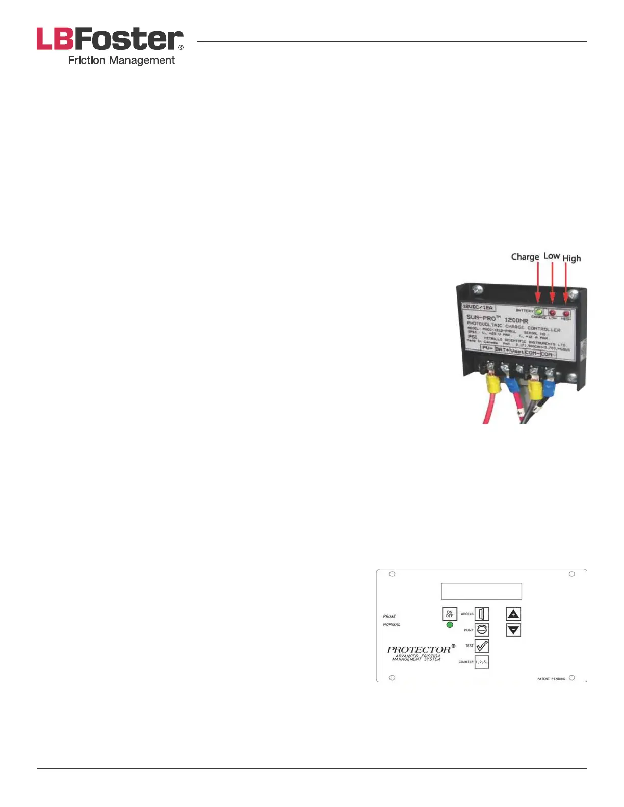
Using the Digital Control Box (DCB)
One of the most important advantages of the PROTECTOR IV unit is its ability to provide precise, controlled
distribution of grease. Both frequency of distribution (the number of wheels that pass before each pump
activation) and duration of distribution (how long distribution pump cycle lasts) can be easily changed directly
on the DCB.
LCD Display
The LCD display is located on the front panel of the DCB. It displays
a digital read-out indicating the DCB’s current operating conditions.
ote: The LCD display will not display characters at temperatures
below -20°C. The DCB will continue to function regardless of the
status display. See that the ON light is green.
J8& )4*& 13**/& CBm& V"#4*#& %./)$/2.2#6(& 54*/& )4*& ./7.S& >2))./& $#&
pressed, then it is possible there is a low voltage condition. If the
voltage is above 11.5 volts the LCD will still function and programming changes can be made, but the control
>.d&5$66&/.)&%.2/)&)4*&54**6#9&J8&)4*&?.6)"1*&$#&6.5&)4*&CBm&5$66&V"#4&3*;@&>2)&)4*&C-m&;$#<6"(&5$66&/.)&.<*3")*9&
Once the voltage is restored to above 12 volts the controller will resume normal operation. If the LCD shows
/.&;$#<6"(&54$6*&CBm&%./)$/2.2#6(&V"#4*#&13**/&"/;&)4*&>"))*3(&?.6)"1*&$#&13*")*3&)4"/&.3&*H2"6&).&^b&?.6)#@&
the LCD is defective.