DMA860E Digital Stepper Drive User Manual
Page | 8
is used, one may use a power supply of lower current rating than that of motor (typically 50%
~
70% of motor current).
The reason is that the drive draws current from the power supply capacitor of the unregulated supply only during the
ON duration of the PWM cycle, but not during the OFF duration. Therefore, the average current withdrawn from
power supply is considerably less than motor current. For example, two 3A motors can be well supplied by one power
supply of 4A rating.
6.2 Power Supply Sharing
Multiple DMA860E drives can share one power supply to reduce cost, if that power supply has enough power capacity.
To avoid cross interference, connect each stepper drive directly to the shared power supply separately. To avoid cross
interference, DO NOT daisy-chain connect the power supply input pins of the Drivers. Instead connect them to power
supply separately.
6.3 Selecting Supply Voltage
The DMA860E is designed to operate within 18 - 80VAC or 24-110VDC voltage input. When selecting a power supply,
besides voltage from the power supply power line voltage fluctuation and back EMF voltage generated during motor
deceleration needs also to be taken into account. Please make sure leaving enough room for power line voltage
fluctuation and back-EMF voltage charge back.
Higher supply voltage can increase motor torque at higher speeds, thus helpful for avoiding losing steps. However,
higher voltage may cause bigger motor vibration at lower speed, and it may also cause over-voltage protection or even
drive damage. Therefore, it is suggested to choose only sufficiently high supply voltage for intended applications.
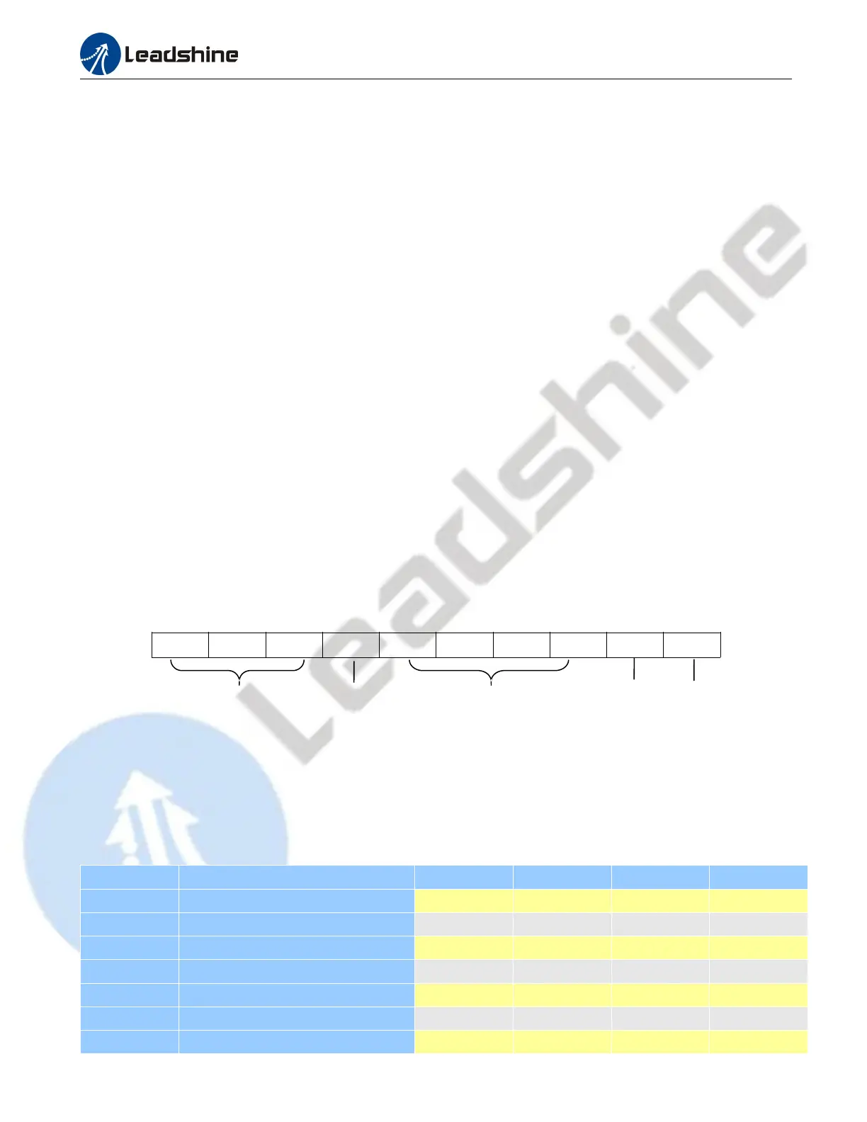
7. DIP Switch Configurations
The DMA860E has one 10-bit DIP switch and one 1-bit selector. The first 10-bit is used to configure settings of micro
step resolution, output current, motor standstill current, pulse type and smoothing time as shown below.
SW1 SW2 SW3 SW4 SW5 SW6 SW7 SW8
SW9
SW10
The second 1-bit selector is located on the top (S2 in figure 2), used to configure the voltage of control signals. For the
safety of optically coupled, the factory setting is 24V, which no need to connect 2K resistors like the old drives, making
it easier to use. When the voltage of the control signal is 5V, the S2 must be set to 5V, otherwise, the motor won't work.
7.1 Microstep Resolution Configurations
Microstep resolution is set by SW5, 6, 7, 8 of the DIP switches as shown in the following table, default means can be
set by Leadshine ProTuner
Microstep Steps/rev.(for 1.8°motor) SW5 SW6 SW7 SW8
2 400(default) ON ON ON ON
4 800 OFF ON ON ON
8 1600 ON OFF ON ON
16 3200 OFF OFF ON ON
32 6400 ON ON OFF ON
64 12800 OFF ON OFF ON
128 25600 ON OFF OFF ON
Idle Current
Output Current
Microstep
Control Mode
Smoothing Time