DMA860E Digital Stepper Drive User Manual
Page | 11
10. Sequence Chart of Control Signals
In order to avoid some fault operations and deviations, PUL, DIR and ENA should abide by some rules, shown as
following diagram:
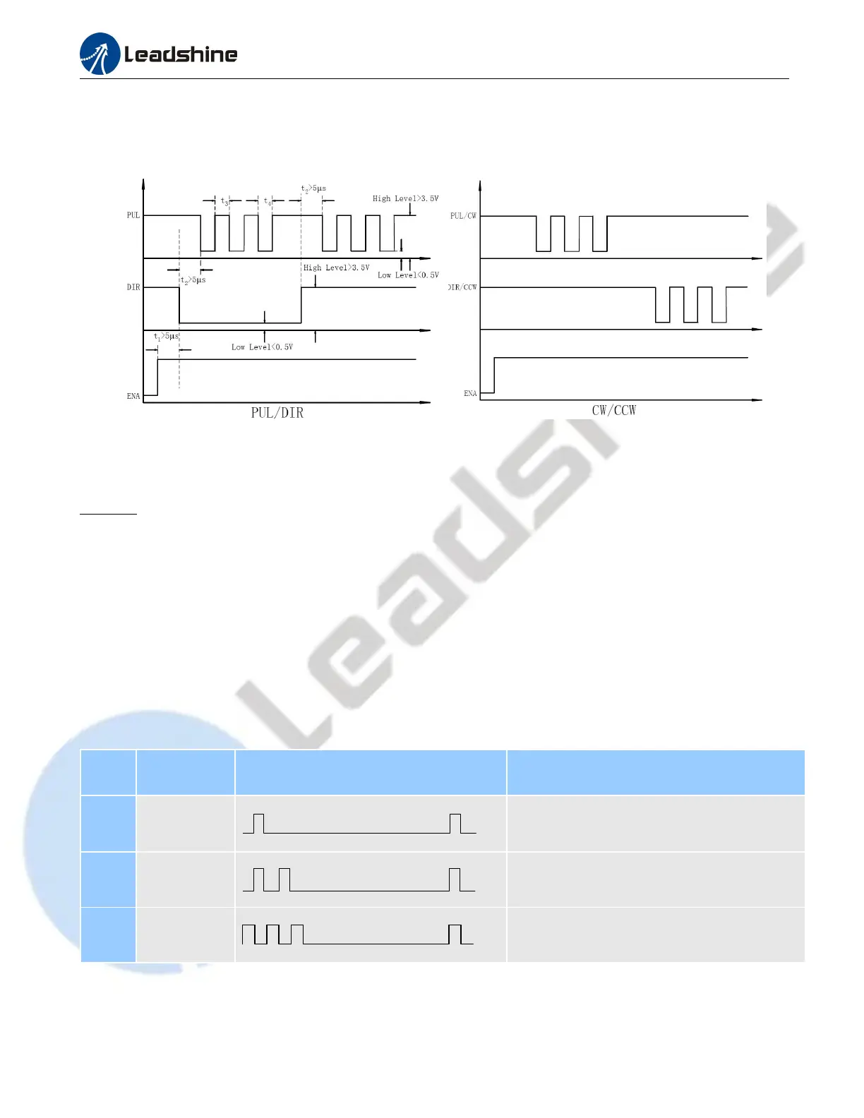
Figure 15: Sequence chart of control signals
Remark:
a) t1: ENA must be ahead of DIR by at least 5ms. Usually, ENA+ and ENA- are NC (not connected). See
“Connector P1 Configurations” for more information.
b) t2: DIR must be ahead of PUL effective edge by 5
s to ensure correct direction;
c) t3: Pulse width not less than 2.5
s;
d) t4: Low level width not less than 2.5
s.
11. Protection Functions
To improve reliability, the drive incorporates some built-in protections features.
Priority
Time(s) of
Blink
Sequence wave of red LED Description
1st 1
Over-current protection activated when peak
current exceeds the limit.
2nd 2
Over-voltage protection activated when drive
working voltage is greater than 160VDC
3nd 3 Reserved.
When above protections are active, the motor shaft will be free or the red LED blinks. Reset the drive by repowering it
to make it function properly after removing above problems.