DMA860E Digital Stepper Drive User Manual
Page | 3
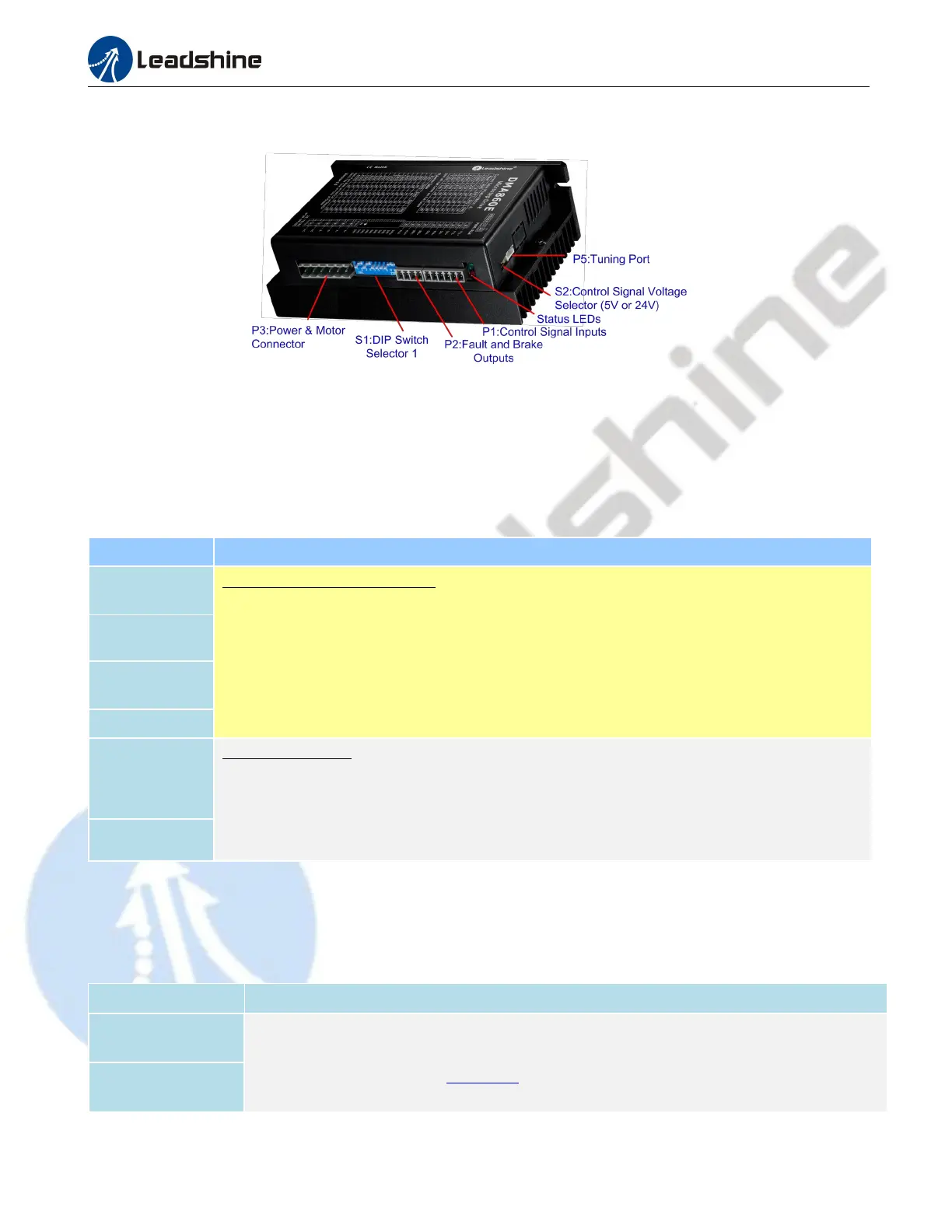
3. Connection Pin Assignments and LED Indication
Figure 2 Connectors, DIP switches, and LED locations
The DMA860E has three connector blocks P1&P2&P3 (see above picture). P1 is for control signals connections, and
P2 is for output signals connections, P3 is for power and motor connections. The following tables are brief descriptions
of the three connectors. More detailed descriptions of the pins and related issues are presented in section 4, 5, 9.
3.1 P1 - Control Connector
PIN Details
PUL+ (CW+)
Pulse and Direction Connection:
(1) Optically isolated, high level 4.5-5V or 24V, low voltage 0-0.5V
(2) Maximum 200 KHz input frequency
(3) The width of PUL signal is at least 2.5μs, duty cycle is recommended 50%
(4) Single pulse (step & direction) or double pulse (CW/CCW) is set by DIP Switch SW9
(5) DIR signal requires advance PUL signal minimum 5 μs in single pulse mode
(6) The factory setting of control signal voltage is 24V, must need to set S2 (figure 2) if it is 5V
PUL- (CW-)
DIR+ (CCW+)
DIR- (CCW-)
ENA+
Enable Connection: (default no connection)
(1) Optically isolated, differential.
(2) Disable the drive by 4.5- 24V input connection; enable the drive by 0-0.5V connection
(3) ENA signal requires advance DIR signal minimum 5μs in single pulse mode
(4) Enable time to be at least 200ms
ENA-
Notes:
(1) Shield cables are required for P1;
(2) Don’t tie P1/P2 cables and P3 cables together.
3.2 P2 - Fault and Brake Output Connector
Pin Details
BRK+
(1) Maximum 30V/100mA output
(4) Brake connection refer to chapter 4.2
BRK-