DMA860E Digital Stepper Drive User Manual
Page | 10
7.4 Smoothing Time Configuration
DMA860E has an advanced feature called control command smoothing to make the input pulse from pulse generator
(controller, PLC, etc.) S-curve acceleration, to improve motion smoothness and high-speed start frequency in many
circumstances. This is achieved through adding filtering time which is configured SW10. Setting to ON to activate the
feature with 12ms acceleration time.
7.3 Automatic Motor Matching & Self Configuration
When powered on a DMA860E will automatically configure itself with the best settings to match the driven stepper
motor for optimal performance. No action is needed.
8. Wiring Notes
In order to improve anti-interference performance of the drive, it is recommended to use twisted pair shield cable.
To prevent noise incurred in PUL/DIR signal, pulse/direction signal wires and motor wires should not be tied up
together. It is better to separate them by at least 10 cm, otherwise the disturbing signals generated by motor will
easily disturb pulse direction signals, causing motor position error, system instability and other failures.
If only one power supply serves multiple DMA860E drives, separately connecting the drives to the power supply
is recommended instead of daisy-chaining.
It is prohibited to pull and plug connector P2 while the drive is powered ON, because there is high current flowing
through motor coils (even when motor is at standstill). Pulling or plugging connector P2 with power on will cause
extremely high back-EMF voltage surge, which may damage the drive.
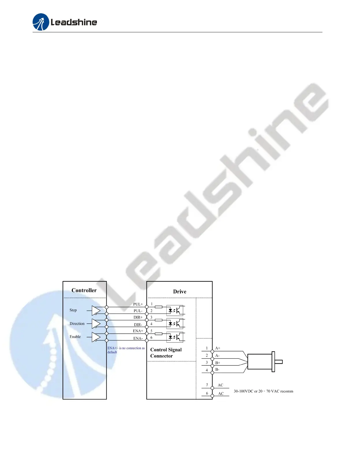
9. Typical Connection
A complete stepping system should include stepping motor, stepping drive, power supply and controller (pulse
generator). A typical connection is shown as below.
Figure 14: Typical connection