DMA860E Digital Stepper Drive User Manual
Page | 4
ALM+
(1) Maximum 30V/100mA output
(2) Sinking or sourcing
(3) The resistance between ALM+ and ALM- is low impedance as default, and will change to
high when the drive goes into error protection.
(4) Fault connection refer to chapter 4.3
ALM-
3.3 P3 - Motor and Power Supply Connector
Pin Function Details
A+, A- Motor Phase A connections. Connect motor A+ wire to A+ Pin; motor A- wire to A-
B+, B- Motor Phase B connections. Connect motor B+ wire to B+ Pin; motor B- wire to B-
AC
Power supply input 18-80VAC or 24-110 VDC(recommended 20-70VAC or 30-90VDC);
No polarity
AC
!
Warning
Warning: Don’t plug or unplug the P1 & P2&P3 terminal block to avoid drive damage or injury when
DMA860E is powered on.
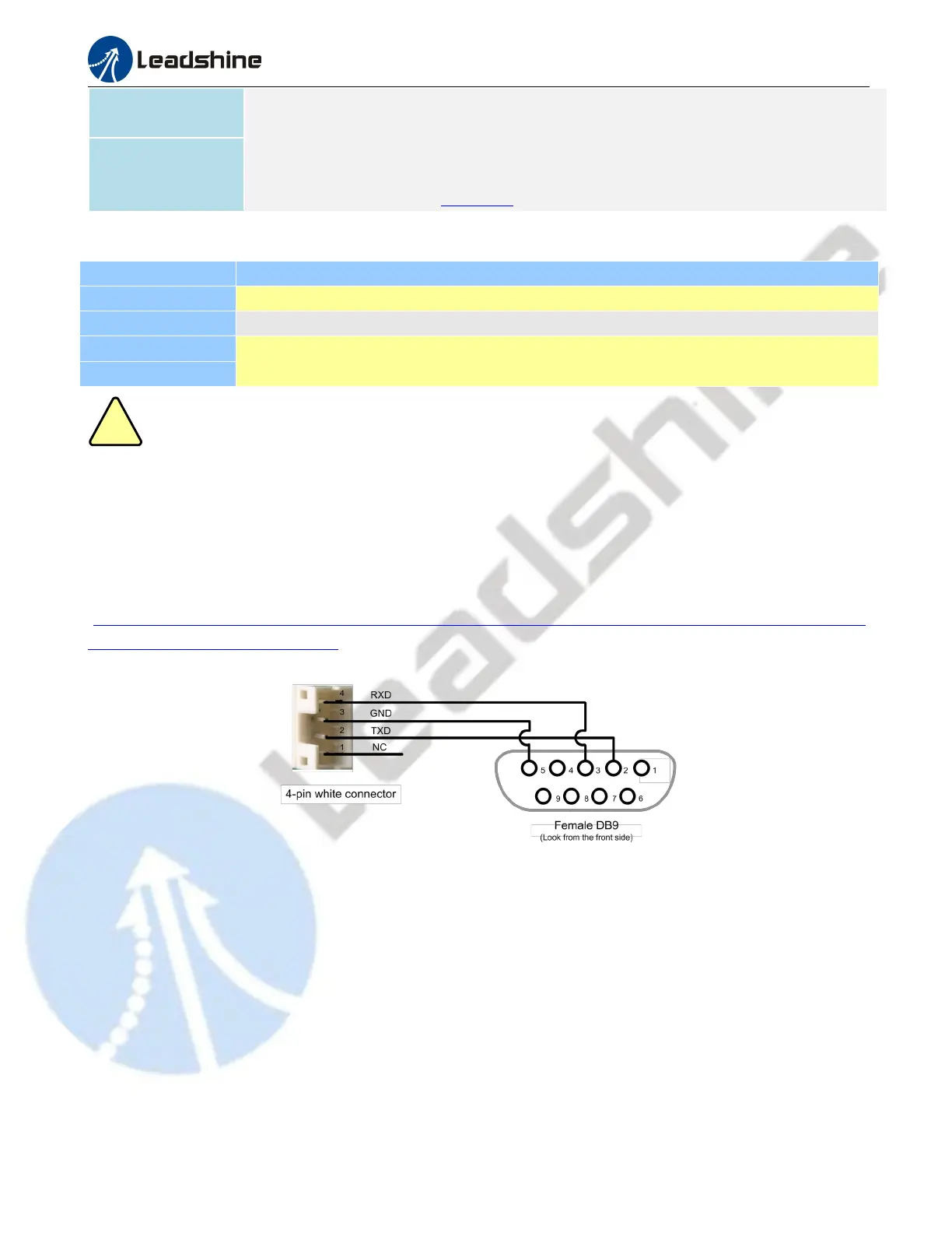
3.4 P4 - Tuning Connector
DMA860E has a tuning port with RS232 to modify the drive parameters, it is just used to modify parameter, not for
equipment control because neither precision nor stability is sufficient. If you need a field bus drive, use a Leadshine
RS485 or EtherCAT type drives:
(http://www.leadshine.com/ProductSubType.aspx?type=products&category=stepper-products&producttype=stepper-dr
ives&subtype=network-stepper-drives
The interface definition is as follows:
Figure 3: RS232 connector
3.5 LED Light Indication
There are two LED lights for DMA860E. The GREEN one is the power indicator which will be always on generally.
The RED one is a protection indicator which will flash 1-2 times in a 3-second period, when protection enabled for a
DMA860E. Different number of flashes indicates different protection type (read section 11 for detail).
4. Control Signal and Output Signal
4.1 Control Signal Connection
The DMA860E can accept can accept differential or single-ended control signals (pulse, direction, and enable) in
open-collector or PNP connection through the P1 connector (figure 2). It is recommend to add an EMI line filter