DMA860E Digital Stepper Drive User Manual
Page | 5
between the power supply and the drive to increase noise immunity for the drive in interference environments.
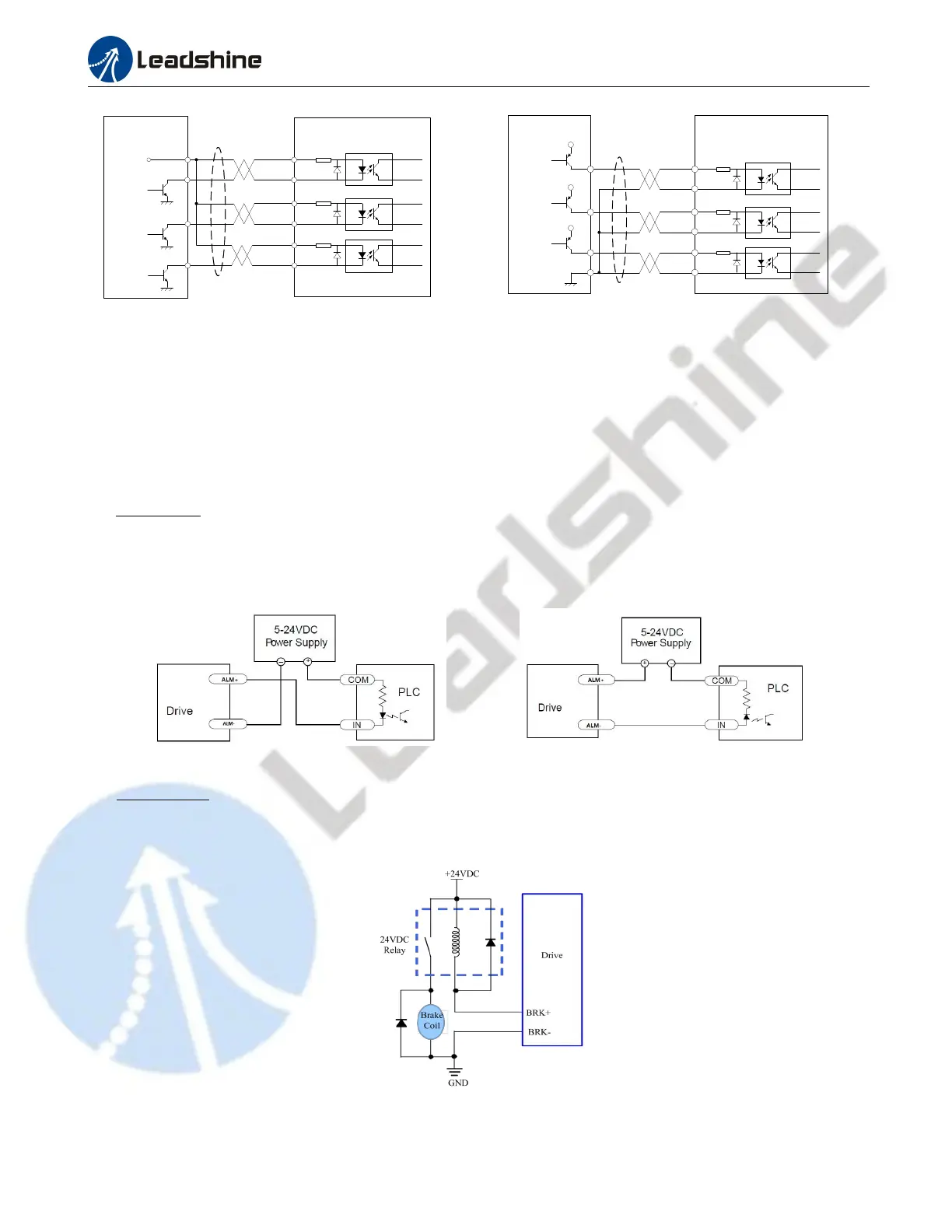
Figure 4: Connections to open-collector signal Figure 5: Connections to PNP signal
(common-anode) (common-cathode)
Notes:
(1) ENA signal is no-connected as default;
(2) Control signal amplitude is 24 V as default. If it is 12 V, please set the S2 (Figure 2) selector switch to 5 V first, then
connect 1KΩ resistor; If it is 5V, please set the S2 to 5V.
4.2 Fault and Brake Output Connection
Fault Output
When over voltage or over current protection happens, DMA860E red status LED light will blink and the impedance
state between ALM+ and ALM- will change (from low to high or high to low depending on configuration) and can thus
be detected. Fault output connection is optional, and it can be connected either in sinking or sourcing.
Figure 6 Sinking output Figure 7 Sourcing output
Brake Control
It is recommended to connect a fly-wheel diode in parallel to a 24VDC relay and brake coil connection. Refer to the
following figure for brake connection.
Figure 8 Brake output
Drive
Controller
VCC
PUL-
PUL+
ENA-
PUL
DIR
ENABLE
DIR-
DIR+
ENA+
Drive
Controller
VCC
PUL-
PUL+
ENA-
PUL
DIR
ENABLE
DIR-
DIR+
ENA+