Code Possible Settings
IMPORTANT
No. Name Default Selection
WARNING!
If the input dened to “Start Sequence” is opened during a sequence, the drive will exit
sequencer mode and will run at the specied standard or alternate speed source (dependent on
drive conguration).
Note
• When input is activated, settings 1...7 override P101
• When TB-13A...TB-13C are congured for Auto References other than MOP, TB-13C overrides
TB-13B, and TB-13B overrides TB-13A. Any other Auto Reference will have priority over MOP.
• Settings 10...14 are only valid in Terminal Strip mode (P100 = 1, 4, 5)
• If Start/Run/Jog Forward and Start/Run/Jog Reverse are both activated, drive will STOP
• If Jog input is activated while the drive is running, the drive will enter Jog mode; when Jog
input is deactivated, drive will STOP
•
An F.AL fault will occur if the Assertion Level switch (ALsw) position does not match the
P120 setting and any of the digital inputs (P121...P123) are set to a value other than 0.
• An F.IL fault will occur under the following conditions:
- TB-13A...TB-13C settings are duplicated (each setting, except 0 and 3, can only be used
once)
- One input is set to “MOP Up” and another is not set to “MOP Down”, or vice-versa.
- One input is set to 10 and another input is set to 11…14.
- One input is set to 11 or 12 and another input is set for 13 or 14.
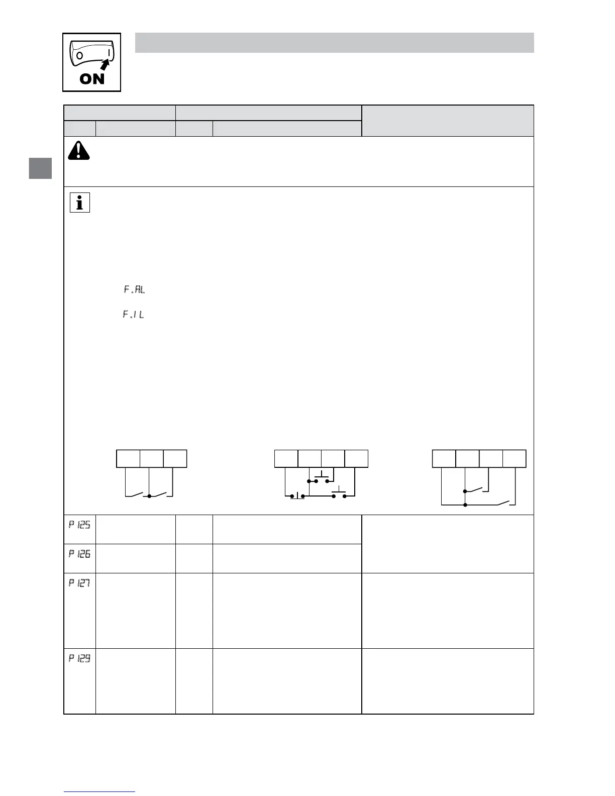
• Typical control circuits are shown below:
- If any input is set to 10, 12 or 14, P112 must be set to 1 for Reverse action to function.
Run / Stop
with Direction
P121 = 10
Start Forward /
Start Reverse
P121 = 11, P122 = 12
Run Forward /
Run Reverse
P121 = 13, P122 = 14
14
13 A
FWD
REV
STOP
RUN
14
13 A13B
RUN
REV
RUN
FWD
FWD
REVSTOP
14
13 A13B
P125
Acceleration
Time 2
20.0 0.0 {s} 3600 • Selected using TB-13A...TB-13C
(P121...P123 = 17)
• For S-ramp accel/decel, adjust
P106
P126
Deceleration
Time 2
20.0 0.0 {s} 3600
P127
Deceleration
Time for
Auxiliary Ramp
to Stop
20.0 0.0 {s} 3600 • Selected using TB-13A...TB-13C
(P121...P123 = 19).
• For S-ramp accel/decel, adjust
P106
• Once executed, this ramp time has
priority over P105 and P126.
P129
Automatic
Accel/Decel rate
switch threshold
0.0 0.0 {Hz} 1000 If Actual Frequency < P129 Use
Accel/decel time #2 (P126/P127)
If Actual Frequency ≥ P129 Use
Accel/decel time #1 (P104/P105)
 Loading...