The diagram previously described suggests the representation “at
levels” of the complete system, in which the riser bus connected
to the IN terminal of SCS/SCS gateway
035 62
assumes the
identification of main Riser while each individual system connected
to the OUT terminal is identified with Local BUS.
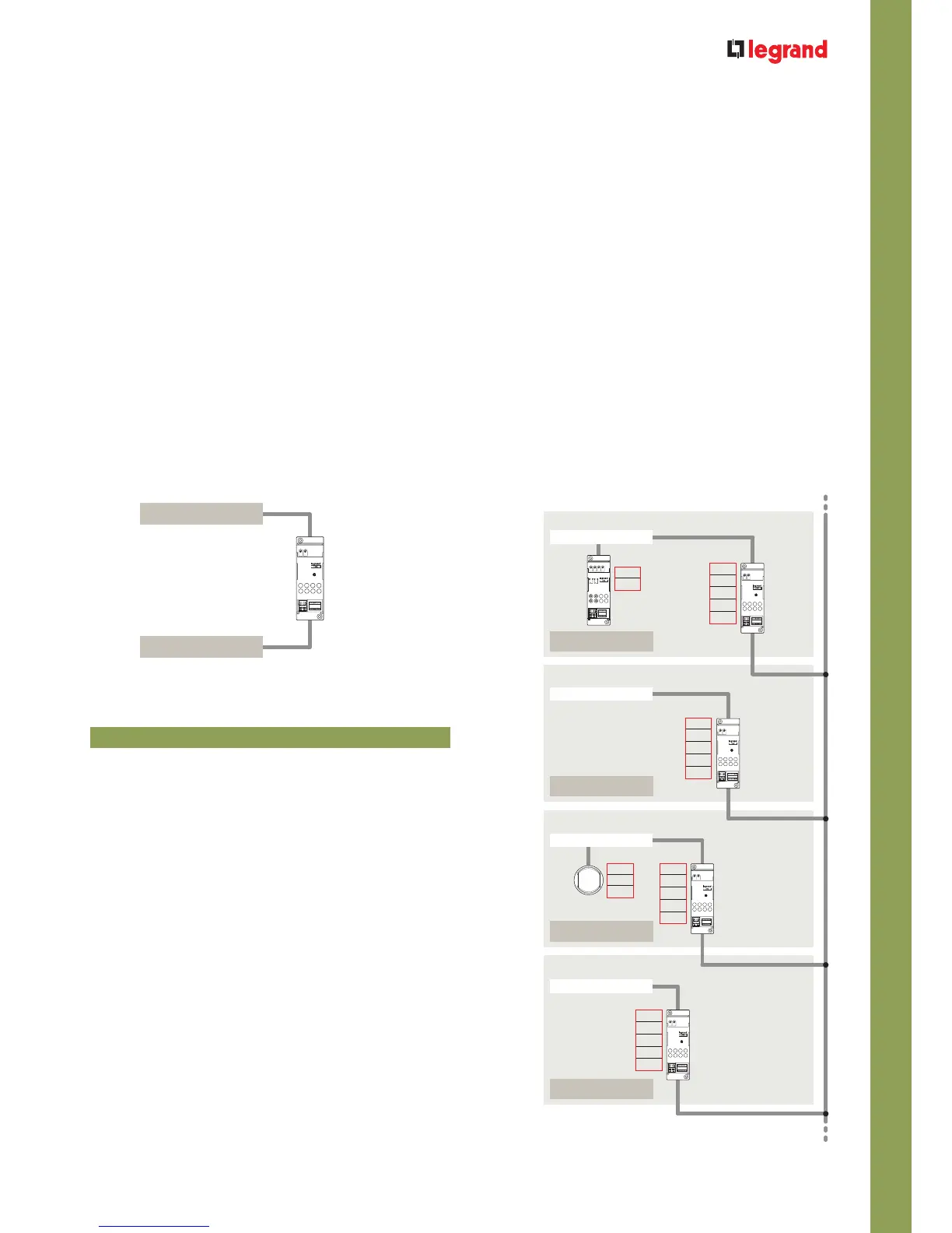
The integrated system previously described can thus be represented
with the following simplified diagram:
OUT
IN
SCS/SCS
gateway
035 62
Local BUS
Main riser
WARNING: configure SCS/SCS gateway
035 62
for operation in “logical extension” mode,
inserting configurator 2 in position M and configuring the addresses of positions I3 and I4 with values
between 01 and 09, as in the following diagram.
It is important to remember that for the correct operation of an integrated system and thus to use the
device virtual configuration mode as well, the Automation system must be made in agreement with
the type of diagram described.
There are 81 configuration addresses for each system (9 light
points for each of the 9 rooms). In the main riser it is possible to
install control devices configured to send GROUP or GENERAL
controls to some or all of the actuators situated in the single
systems and in the same main riser. POINT-POINT controls
generated inside each single system and on the main riser can
reach the actuators situated in the whole system only if they
are sent from the appropriately configured cross control device
situated on the main riser or on one of the single systems
(max 9) connected. In this case it is possible to address up to a
maximum of 810 devices (81 devices per system x 9 systems +
81 devices on the main riser). If you need to control and execute
the centralised management of the system with Web Server,
Touch Screen and Control Unit, these devices will have to be
installed in the main riser.
FEATURES AND RULES FOR INSTALLATION
Using the control of the system No. 3 it is possible to control the actuator in the system No. 1.
If three or more systems (up to a maximum of 9) must be combined,
these must be connected by means of SCS/SCS gateway
035 62
with a common bus, which from now on we will call “riser”, on
which the control, activation and management (for example Touch
Screen) devices can also be installed because they belong to the My
Home Legrand Automation system. The riser cannot be made, for
example, with a Burglar-alarm or 2 wire Video door entry system.
For the combination of different systems see the indications given in
the
Integration and Control section.
Max 81 addresses
Main riser
Max 81 addresses
Local BUS
Actuator
Max 81 addresses
Control
Max 81 addresses
Local BUS
Local BUS
Local BUS
Automation system No. 2
Automation system No. 1
I1 = –
I2 = –
I3 = –
I4 = 1
M = 2
I1 = –
I2 = –
I3 = –
I4 = 2
M = 2
A = 3
PL = 6
I1 = –
I2 = –
I3 = –
I4 = 3
M = 2
A = 3
PL = 6
I = 1
I1 = –
I2 = –
I3 = –
I4 = 4
M = 2