Leica ComGate10, Operation
32
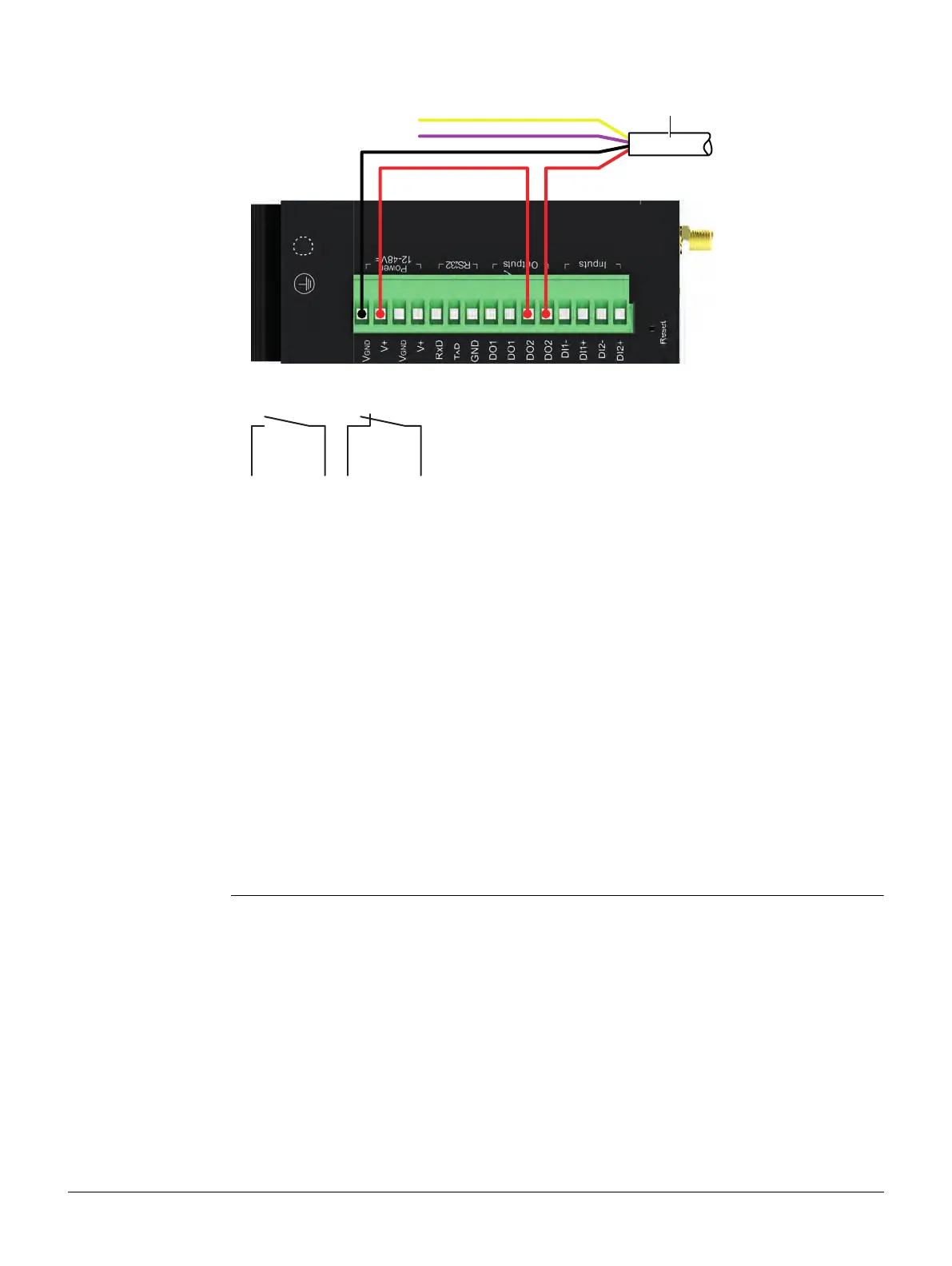
Setup of the digital
I/O
Drawing and description of the two coupling relays which can be used to connect
warning devices or restart the instrument from a remote position.
Only DO1 should be used to connect a warning device.
DO2 should be used to switch the instrument off/on.
Relay specifications
Power supply for instrument
a) For example:
GEV271
Max. current: 1 A
Max. switching voltage: 60 V AC
DO1 Normally Closed, it is connected when the relay coil is off.
DO2 Normally Open, it is connected when the relay coil is on.
• Limiting continuous current: 1 A
• Maximum switching voltage: 60 V DC, 42 V AC (Vrms)
• Maximum switching capacity: 60 W
• Instrument can be switched off/on automatically.
• Bridge to DO2 has to be set up.
• Use GeoMoS, Leica ComBox Manager or SMS for switching the instru-
ment.
• Switch box will be obsolete.
006193_001
a
DO2DO1
006194_001