5. Assembling the microscope – tr Ansmit ted light illuminAtion cArrier
5.8.2 Fixed transmitted light illuminator arm
Assembling the transmitted light column
• Attachthetransmitted light illumination column (Fig. 30.1)
and fasten it with 4 screws (Fig. 30.2).
Attaching the condensers
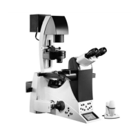
• Screw the S80/0.30 condenser (Fig. 28.2) or S40/0.45
condenser (Fig. 28.1) onto the condenser holder of the
(Fig. 29.2) transmitted light illuminator arm from below.
Fig. 28: Condensers
1 S40/0.45 condenser
2 S80/0.30 condenser
1 2
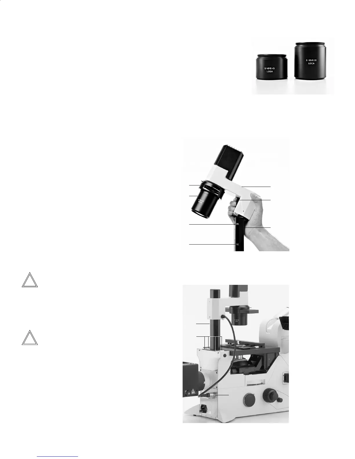
Inserting the transmitted light illuminator arm
• Insert the transmitted light illuminator arm into the col-
umn from above by pressing and holding down the stop
lever for condenser height adjustment (Fig. 29.5).
• Position the transmitted light illuminator arm (Fig. 29.3)
onto the transmitted light illumination column based on
the condenser being used (S40/0.45 or S80/0.30) (Fig. 29.4)
and release the stop lever. (Also see the following note.)
The marks (Fig. 29.6) pertain to a liquid height of 15 mm.
For stands with double marks, the upper and lower lines
represent a range with different liquid heights.
• Make sure that the transmitted light illuminator arm is
engaged.
• Connecttheelectronicscabletotheport(Fig.30.3).
Note:
For the stands with 3-plate mechanical stages, position the
illuminator arm 25 mm below the marks, as the illumination
axis is installed 25 mm higher on an adapter than on the
fixed stage.
Note:
A screw on the transmitted light illumination column pre-
vents the condenser from colliding with the specimen
stage. If necessary, move the screw into the higher of the
two openings, if using the S80/0.30 condenser.
2
1
6
6
3
5
4
Fig. 29: Transmitted light illumination unit with condenser
1 Condenser
2 Condenser holder
3 Transmitted light illuminator arm
4 Transmitted light illumination column
5 Stop lever for condenser height adjustment
6 Labels
Fig. 30: Assembling the transmitted light illumination column
1 Transmitted light illumination column
2 Fastening screws
3 Cable connection
1
2
3
23
 Loading...