5. Assembling the microscope – specimen stAges
5.2 Assembling the specimen stage
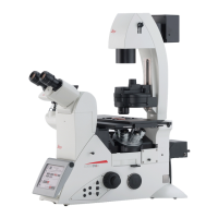
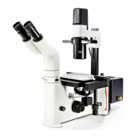
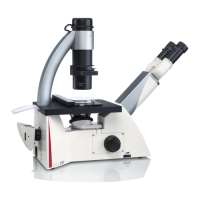
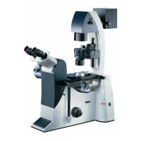
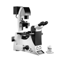
There is a wide variety of available specimen stages.
The accompanying figures depict a few examples.
The assembly of each of these stages is identical. The
stages are permanently affixed to the microscope using 3
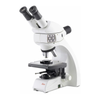
screws (Fig. 14). In the case of fixed stages, a mechanical
stage can be attached (Fig. 15).
! Caution!
Screw lengths may vary. The following applies to the ship-
ment of different screws: Always use the shorter of the
3 screws for the front hole and both screws of equal length
for the rear holes.
• Alignthestagesothatbothholespointbacktowardsthe
illumination axis and the single hole is facing in the direc-
tion of the tube.
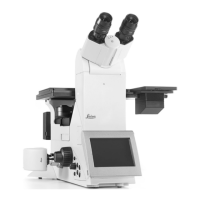
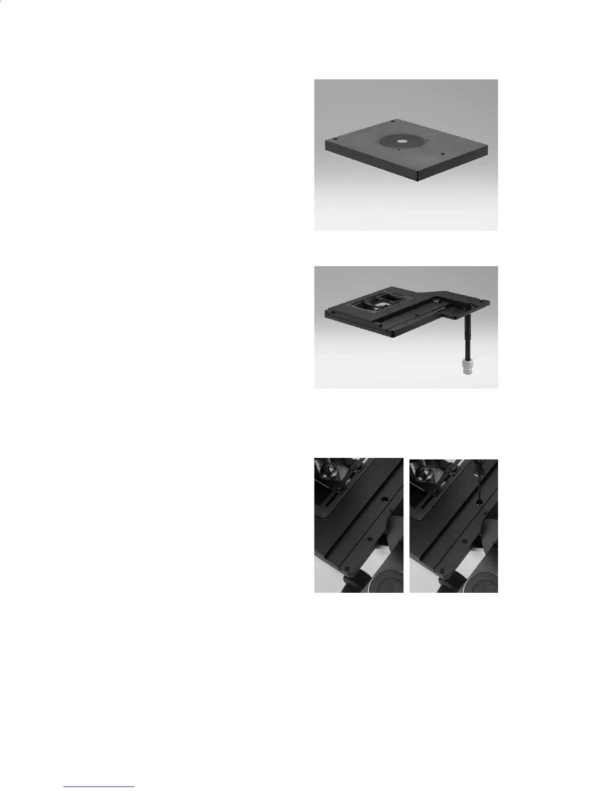
• Align the fastening holes in the stage with the holes in
the contact surface. If the holes are not visible, as in the
case of the 3-plated cross-stage or scanning stage, gen-
tly move the upper tabletop until the opening is visible.
• Startbygentlyturningthefrontscrewusingtheprovided
3 mm hexagonal key. It is important that the shorter of the
3 screws is always placed in the front hole, because a
screw that is too long can damage the focus hub.
• Then,tightenbothrearscrews.
• Finally,retightenthefrontscrew.
Fig. 12: Fixed stage
Fig. 13: Mechanical 3-plate stage
Fig. 14: a, b assembly screws for 3-plate cross-stage
a b
16
 Loading...