VARIABLY SPACED HALF-BLIND DOVETAIL PROCEDURES
32
Chapter 9 Super Jig-12-18-24 User Guide
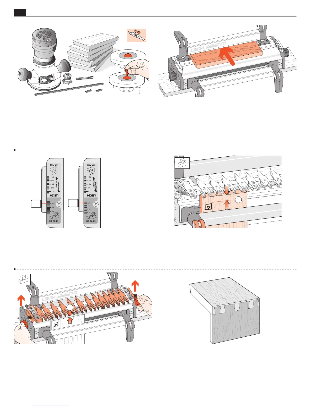
9-8 Routing a Test Joint Use the e7-Bush or a
7
⁄16"[11,1mm]
diameter bush (min. depth
1
⁄4" see page 67) and No.120-8
1
⁄2"[12,7mm] 14° dovetail bit. (80-series bits cut too deep for
3
⁄4"[20mm] boards, see HB bits, Appendix II). Select several pieces
of
3
⁄4"x5
1
⁄2"[20x140mm] x about 8"[200mm], and the plastic
bridge. Note: Half-blind pin boards must be minimum ½"[13mm]
thick to clamp. Thinner boards; see 9-21.
9-10 Mount the finger assembly on the support brackets in the
H
HB TAILS mode, flat on the spacer board, scales set on the
thickness of the tail board (
3
⁄4"[20mm] in this instance).
The
H
HB TAILS scale is always set at the tail board thickness.
Max tailboard thisckness is 1" however max scale setting is 3/4".
9-11 Measure and mark a line on the inside face of the tail board
to the bit’s depth of cut as in 9-2. Clamp this test tail board in
the left front clamp, against the side stop with the top edge flush
under the guidefingers, and the inside face
i
of the drawer side
away from the jig.
�
9-12 Unlock and raise the finger assembly support brackets
slightly so that the finger assembly is about
1
⁄16"[2mm]
above
the boards. This will allow easy movement of the guidefingers.
1
9-13 The following joint design is suggested for this trial. It has a
typical and traditional even layout of pins, with half-pins at each
edge. The Leigh jig, however, allows for an infinite variety of joint
designs, and boards of different thicknesses can be joined to each
other as shown in this illustration. Before attempting joints of
asymmetrical design, see chapter 12.
9-9 Clamp the spacer board in the rear clamp.
 Loading...