33
VARIABLY SPACED HALF-BLIND DOVETAIL PROCEDURES
Chapter 9Super Jig-12-18-24 User Guide
9-14 Ignoring the extreme outer guidefinger next to the scale
(which just supports the router), loosen enough of the adja-
cent guides to give the required pin socket layout. The half-pin
guidefinger position illustrated will give a half-pin socket profile
like that shown (dotted lines).
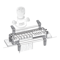
9-15 If the gaps between the guidefinger tails are wider than about
1
⁄8"[3mm], mark off and cut some pieces of bridge extrusion
to
fit into the slots in the ends of the guidefinger tails. Cut the pieces
a "bare"
1
⁄8"[3mm] more than the distance between the fingers
.
They are a firm friction fit.
After completing a project, save the bridge pieces for future use.
1
2
9-16 Remember to tighten any loose guidefingers. Lower the
finger assembly back onto the spacer board and workpiece. It
must touch the workpiece or the depth of cut will vary and the
joint won’t fit. The scale should be set on the tailboard thickness,
in this case
3
⁄4"[20mm].
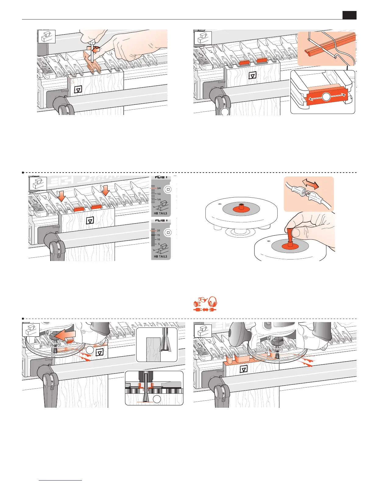
9-17 Attach the provided e7-Bush or a
7
⁄16"[11,1mm] diameter
bush securely to the router. No guidebush adjustment is required
with half-blind dovetails.
Fit the selected dovetail bit to the router.
REMEMBER SAFETY!
9-18
Adjust the bit height until the bit tip is
level with the marked line
. For the first light cut
move the router from right to left. Make sure you control it firmly,
because it is driven in this direction by the bit. Only the tip of
the bit should be cutting on the first cut
. This back or climb
routing leaves a very clean shoulder in side grain.
9-19 Now rout in and out from left to right following the guides
and bridge pieces to rout out the pin sockets, leaving the tails.
See Hints and Tips 15-11. Remove the tail board.
2
1