TM
2.1 Auto Glide Key Pad Installation
TM
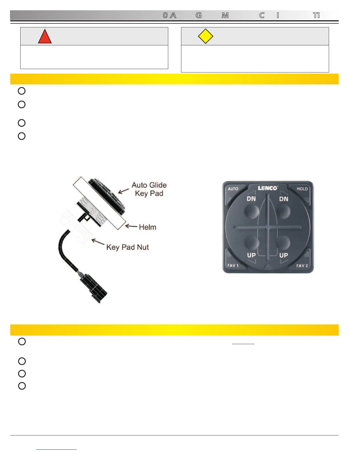
Determine where the Auto Glide key pad will be installed. Must have a 2.75” by 2.75” clearance on helm.
Before cutting, make sure the area inside the helm is clear of wires and other equipment that could be damaged. Find
center of key pad location and cut a circular opening using a 2” (5.08cm) hole saw (hole must be 2” (5.08cm)).
Drop key pad into 2” (5.08cm) hole.
From underneath the helm, hand tighten the large white key pad nut onto the back of the key pad. Make sure the key
pad is securely installed. (See Figure 2.1.1) Note: key pad nut can be flipped to accommodate helm thickness.
2.0 AUTO GLIDE MECHANICAL INSTALLATION
5
AUTO GLIDE
1
2.2 Replacing Existing 123 LED Indicator / 124 Standard Key Pad
From underneath the helm, disconnect the existing key pad from the control box. Squeeze the release mechanism on
the black wire and pull it away from the existing key pad.
Unscrew the four nylon nuts from the existing key pad posts.
From the top side of the helm, remove existing key pad.
TM
Install the Auto Glide key pad by simply dropping it into the existing 2” (5.08cm) hole and screw the large white key
pad nut onto the back of the key pad. Make sure the key pad is securely installed.
WARNING
!
Before cutting, make sure the inside the area inside the
helm is clear of wires and other equipment that could
be damaged.
CAUTION
Please read through the instructions in their entirety
prior to beginning installation! Proper function of this
product cannot be assured unless you follow these
instructions.
CAUTION
Figure 2.1.1 Figure 2.1.2
2
3
4
1
2
3
4
Rev 03-10-11
 Loading...