3.0 AUTO GLIDE ELECTRICAL INSTALLATION
7
TM
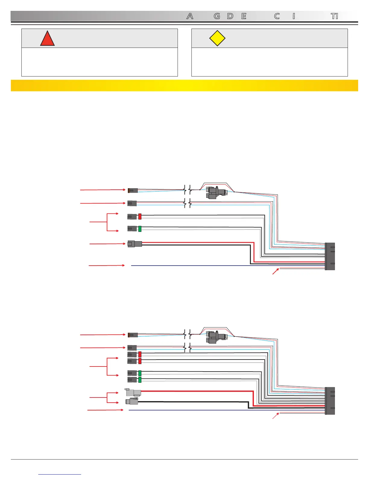
3.1 Auto Glide Control Box Harness Overview
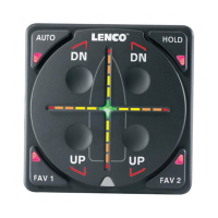
AUTO GLIDE
TM
There are two types of Auto Glide Control Box Harnesses:
TM
- Single Actuator Auto Glide Control Box Harness for systems with two actuators (See Figure 3.1.1)
TM
- Dual Actuator Auto Glide Control Box Harness for systems with four actuators (See Figure 3.1.2)
TM
Each Auto Glide Control Box Harness has 6 sets of electrical connections coming out of the 30 pin Cinch connector.
WARNING
!
The power connections should always be the last
connection made.
Power connections should only be made while the
battery switch in the OFF position.
CAUTION
Please read through the instructions in their entirety
prior to beginning installation! Proper function of this
product cannot be assured unless you follow these
instructions.
CAUTION
Single Actuator Control Box Harness
Dual Actuator Control Box Harness
NMEA
0183(+/-)
DUAL ACTUATOR
LEAD CONNECTIONS
POWER CABLES
IGNITION
SENSE WIRE
NMEA
0183(+/-)
CANBUS #1
(Engine Data / GPS Data Source)
CANBUS #2
(Key Pad / GPS Data Source)
SINGLE ACTUATOR
LEAD CONNECTIONS
POWER CABLES
IGNITION
SENSE WIRE
1
2
DTP
Figure 3.1.1
Figure 3.1.2
CANBUS #1
(Engine Data / GPS Data Source)
CANBUS #2
(Key Pad / GPS Data Source)
Rev 03-10-11
 Loading...