3.0 AUTO GLIDE ELECTRICAL INSTALLATION
9
AUTO GLIDE
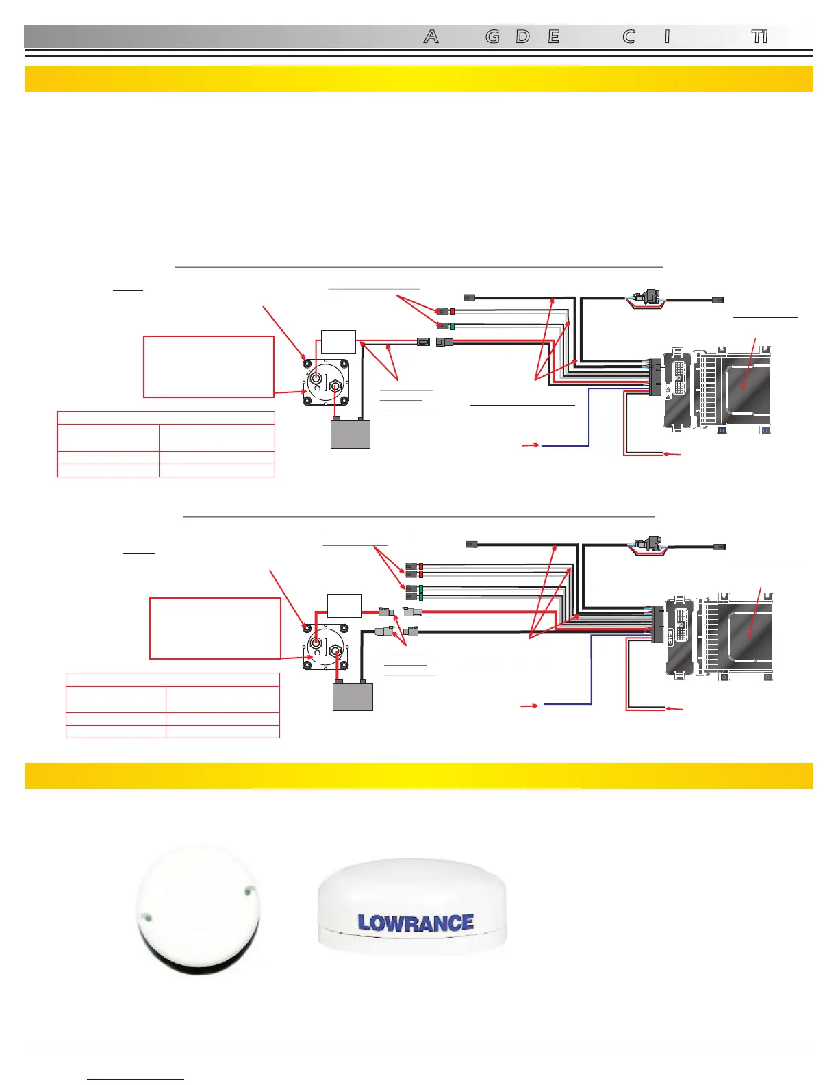
3.3 Battery Switch Requirements
Lenco Marine recommends that the Auto Glide's main power input be connected to a battery switch to prevent unnecessary
drain on your battery while the Auto Glide is in STANDBY MODE. The Auto Glide Control Box and Key Pad draw a very small
amount of power (35mA) when it is in STANDBY MODE, but this small current draw will still drain your battery over time. In
addition, if the Auto Glide is powering a GPS antenna on CAN 2 (Key Pad Leads), then the amp draw increases and your
battery will drain even quicker.
Disconnecting power to the Auto Glide through a battery switch when your boat is not being used will eliminate any current
draw from your battery. The following illustrations outline how Lenco Marine recommends you connect the Auto Glide to a
battery switch.
3.4 Optional GPS (Stand Alone) Antenna Installation
The GPS module can be installed on any flat surface as long as there is room behind the mounting surface for the screws.
See Figures 3.4.1-3.4.2 on page 10 for more information. The optional Lenco Marine 70567-001 GPS Antenna/Receiver
Mounting Bracket kit (See Section 3.5 on page 11) allows you to install the antenna on any vertical surface.
Rev 03-10-11
The LGC -4000 (NMEA 2000) Antenna/Receiver consists of a male threaded cable connector and the GPS Module. The GPS
Module contains a 16-parallel channel GPS+WAAS receiver. The cable length from the connector to the GPS module is 18
inches (45.7 cm).
STANDARD LENCO
SINGLE ACTUATOR TRIM TAB INSTALLATION
AUTO GLIDE
CONTROL BOX
LENCO P/N
30255-001
NMEA0183 INPUTS
0183-
0183+
AUTO GLIDE
CONTROL BOX HARNESS
SINGLE ACTUATOR/TAB:
LENCO P/N: 30248-001
(4 FT)
IGNITION INPUT
I
N
P
U
T
O
U
T
P
U
T
1
2
DTP
BATTERY
1
2
DTP
DTP POWER
HARNESS
LENCO P/N:
30140-00X
(3 FT / 6 FT)
TRIM TAB ACTUATOR
CONNECTIONS
BATTERY
20AMP
FUSE/
BREAKER
MAIN POWER MUST
BE CONNECTED
TO BATTERY SWITCH
OR PROPERLY RATED
ON/OFF SWITCH
NOTE: TURN BATTERY SWITCH “OFF”
WHEN BOAT IS NOT BEING USED TO
ELIMINATE DRAIN ON BATTERY.
AUTO GLIDE
CONTROL BOX
LENCO P/N
30256-001
NMEA0183 INPUTS
STANDARD LENCO DUAL ACTUATOR TRIM TAB INSTALLATION
0183-
0183+
AUTO GLIDE
CONTROL BOX HARNESS
DUAL ACTUATOR/TAB:
LENCO P/N: 30247-001
(4 FT)
IGNITION INPUT
I
N
P
U
T
O
U
T
P
U
T
BATTERY
HD POWER
HARNESS
LENCO P/N:
10249-001
(6 FT)
TRIM TAB ACTUATOR
CONNECTIONS
BATTERY
MAIN POWER MUST
BE CONNECTED
TO BATTERY SWITCH
OR PROPERLY RATED
ON/OFF SWITCH
NOTE: TURN BATTERY SWITCH “OFF”
WHEN BOAT IS NOT BEING USED TO
ELIMINATE DRAIN ON BATTERY.
30AMP
FUSE/
BREAKER