52
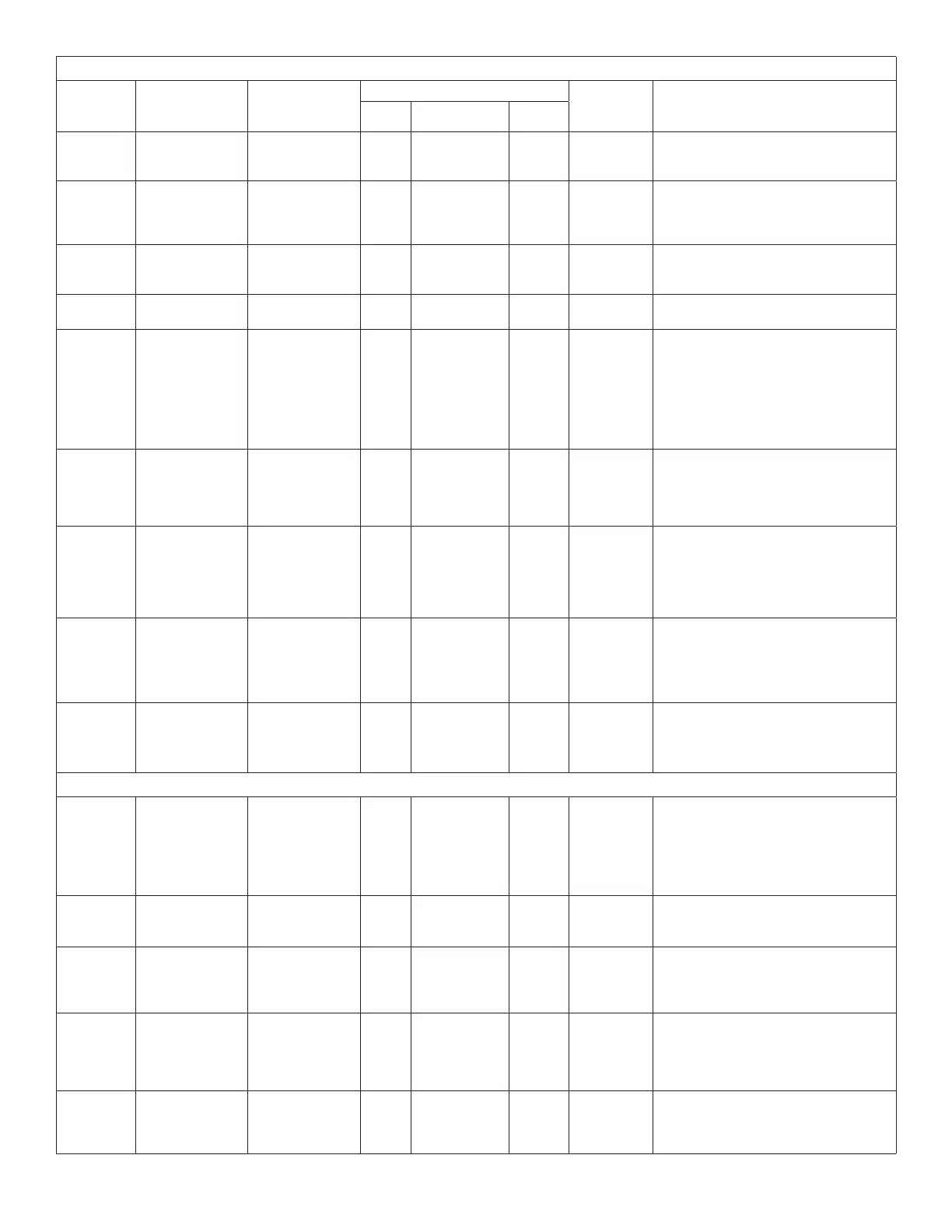
Table 12. CORE Control System Unit Parameters
Control
Parameter
No
Screen Name
Parameter Short
Description
Control Value
Units Description
Min. Default Max.
66
HT GAS BLR ON
DELAY
Gas Blower
On Delay After
Heating Demand
8
System
Dependent
60 Seconds
The time before the blower turns on after
a heating demand.
67
HT GAS BLR
OFF DLAY
Gas Blower
Off Delay After
Heading Demand
Termination
80
System
Dependent
300 Seconds
The time the blower stays on after the
heating demand is terminated.
69
HT GAS HI FIRE
DLAY
Gas Minimum
Low Fire Time
Prior to High Fire
30 100 300 Seconds
Theminimumlowretimebeforehigh
reisallowed.
70
HT GAS OFF
DELAY
Heating Off Delay
Timer
30 100 300 Seconds Heating off delay.
71
MAX CAI PRF
SW OCC
Maximum
Combustion
Air Inducer
Proof Switch
Occurrence
Setting Prior To
Service Output
Energized.
1 3 5 Occurrences
Service relay activation. Maximum
combustion air Inducer proof switch
occurrences stored before service output
is energized.
72
MAX CAI NO
PRF OCC
Maximum
Combustion
Air Inducer
Proof Switch
Occurrences
1 3 15 Occurrences
After the initial maximum combustion air
Inducer proof switch closure, the system
will continue to monitor the pressure
switch and set alarm if three open
occurrences are detected
73
MAX GV SENSE
OCC
Maximum Gas
Valve Sense
Occurrences
Stored Prior to
Service Output Is
Energized
1 3 5 Occurrences
Service output activation. Maximum gas
valve sense occurrences stored before
service output is energized.
NOTE: Heating stage is not locked out.
74
HT GAS STG UP
TMR
Gas Stage Up
Timer
0 912 3600 Seconds
• Stage-up timer. The maximum time
that lower stage runs before calling
next heat stage. Used in room
sensor applications.
• Disabled if set to 0.
75
HT GAS STG
DWN TMR
Gas Stage Down
Timer
0 0 3600 Seconds
• Time delay before a lower stage
turns off following a higher stage
termination.
• Used in room sensor applications.
Block 4 Cooling Parameters
78
COOL DOWN
DELAY
Cool Down Time
Delay
0 30 136 Minutes
• Cool down time delay. Time that Y2
is ignored during cool down period
(whenrstoccupied+cooldemand)
• This delay is only used if an
economizer is used and the outdoor
air is suitable.
79
COOL BLR ON
DELAY
Cooling Blower
On Time Delay
0
See section
3.3.9. on page
20 for defaults.
60 Seconds
The time before the blower turns on after
a cooling demand.
80
COOL BLR OFF
DELAY
Cooling Blower
Off Time Delay
0
See section
3.3.10. on
page 20 for
defaults.
240 Seconds
The time the blower stays on after the
cooling demand is lost.
81
MAX FREEZE
STAT OCC
Maximum Freeze
Thermostat
Occurrence
1 3 3 Occurrences
Service output activation and compressor
lockout. Maximum freeze thermostat
occurrences are stored before service
relay is energized and compressor is
locked-out.
82
COND FAN
RESTRT DLY
Condenser Fan
Restart Time
Delay
0 6 16 Seconds
Low ambient anti-windmilling condenser
fan delay. The time period that the last
operating fan is turned off before starting
the next fan.