CONFIGURATION ID 2
Not Installed = N
Installed on M4 = C
Installed on DDC
Controller = D
Dirty Filter Switch (S27) [2]
Not Installed = N
Installed on M4 = C
Installed on DDC Controller = D
Not Installed =
N
Installed = Y
[5] Phase / Voltage
Detection
N Not Installed =
Enabled Internal (Lennox) = 1
External (A42) Phase Detection = 2
on DI-2
External (A42) Phase Detection = 3
on DI-3
N = Not Installed
Y = Installed
[8] Load Shedding
N = Not Installed
G = Global (P297 - pin 9)
2 = Installed on DI-2
3 = Installed on DI-3
[9] Field Electric Heat
[1]
Air Flow Proving
Switch (S52)
[3]
Overflow Switch
(S149 / S179)
[4]
Motor Overload
Switch (S42)
Not Installed = N
Installed on DI-2 = 2
Installed on DI-3 = 3
[7] Zone Bypass Damper
N = Not Installed
Y = Installed
[6] IAQ Options
N = Not Installed
1 = UV Lamp Installed
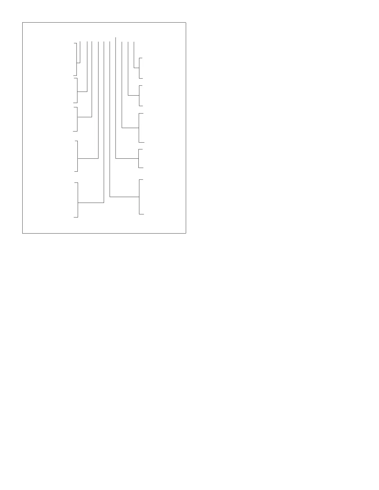
1 2 3 4 5 6 7 8 9 10
2 = Bipolar Ionizer Installed
3 = UV Lamp and Bipolar
Ionizer Installed
N = Not Installed
Y = Installed
[10] Wi-Fi Capability
Figure 6. CongurationID2