EasyManua.ls Logo

Lennox G60UH User Manual

Lennox G60UH
62 pages
To Next Page IconTo Next Page
Page #1 background imageLoading...
Page #1 background image
Page 1
© 2002 Lennox Industries Inc.
Corp. 0204−L2
Revised 11−2006
G60UH(X)
Service Literature
G60UH(X) SERIES UNITS
G60UH(X) series units are mid−efficiency gas furnaces
used for upflow or horizontal applications only, manufac-
tured with Lennox Duralok Plus heat exchangers formed of
aluminized steel. G60UH(X) units are available in heating
capacities of 44,000 to 132,000 Btuh and cooling applica-
tions up to 5 tons. Refer to Engineering Handbook for prop-
er sizing.
Units are factory equipped for use with natural gas. Kits are
available for conversion to LPG operation. G60UH(X) model
units are equipped with the Two−Stage / Variable Speed Inte-
grated SureLight control. G60UH(X) unit meets the Califor-
nia Nitrogen Oxides (NO
x
) Standards and California Sea-
sonal Efficiency requirements. All units use a redundant gas
valve to assure safety shut−off as required by C.S.A.
All specifications in this manual are subject to change. Pro-
cedures outlined in this manual are presented as a recom-
mendation only and do not supersede or replace local or
state codes. In the absence of local or state codes, the
guidelines and procedures outlined in this manual (except
where noted) are recommendations only and do not consti-
tute code.
TABLE OF CONTENTS
Specifications Page 2. . . . . . . . . . . . . . . . . . . . . . . . . . . . .
Blower Data Page 5. . . . . . . . . . . . . . . . . . . . . . . . . . . . . .
High Altitude Page 10. . . . . . . . . . . . . . . . . . . . . . . . . . . . .
Parts Identification Page 11. . . . . . . . . . . . . . . . . . . . . . . .
I Unit Components Page 12. . . . . . . . . . . . . . . . . . . . . . .
II Installation Page 24. . . . . . . . . . . . . . . . . . . . . . . . . . . .
III Start Up Page 24. . . . . . . . . . . . . . . . . . . . . . . . . . . . . . .
IV Heating System Service Checks Page 25. . . . . . . . .
V Typical Operating Characteristics Page 27. . . . . . . . .
VI Maintenance Page 28. . . . . . . . . . . . . . . . . . . . . . . . . .
VII Wiring and Sequence of Operation Page 30. . . . . .
VIII Field Wiring and Jumper Setting Page 46. . . . . . . .
IX Control Board Troubleshooting Page 50. . . . . . . . . .
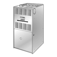
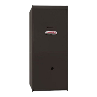
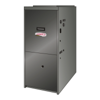
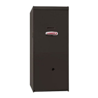
G60UH−1 MODEL SHOWN
IMPORTANT
Improper installation, adjustment, alteration, service
or maintenance can cause property damage, person-
al injury or loss of life. Installation and service must
be performed by a qualified installer, service agency
or the gas supplier.
WARNING
Electric shock hazard. Can cause injury
or death. Before attempting to perform
any service or maintenance, turn the
electrical power to unit OFF at discon-
nect switch(es). Unit may have multiple
power supplies.
WARNING
Sharp edges.
Be careful when servicing unit to avoid sharp edges
which may result in personal injury.

Questions and Answers:

Lennox G60UH Specifications

General IconGeneral
TypeGas Furnace
Blower TypeVariable Speed
Ignition TypeDirect Spark Ignition
WarrantyLimited Lifetime Heat Exchanger Warranty, 5-year Limited Warranty on covered components
Fuel TypeNatural Gas
Blower MotorVariable Speed
StagesTwo-stage heating

Summary

UNIT INFORMATION

G60UH(X) SERIES UNITS

General overview of the G60UH(X) furnace series.

IMPORTANT SAFETY INFORMATION

Critical warnings regarding installation, service, and potential hazards.

SPECIFICATIONS

Gas Heating Performance

Key performance data including input, output, and AFUE ratings.

Connections and Blower Specifications

Physical connection sizes and blower motor details.

BLOWER DATA

G60UH-24A-045 and G60UH-24A-070 PERFORMANCE

Air volume and watt data for specific G60UH models.

BLOWER DATA Cont.

G60UH-36A-070 and G60UH-36B-090 PERFORMANCE

Air volume and watt data for specific G60UH models.

HIGH ALTITUDE / MANIFOLD PRESSURE INFORMATION

PARTS ARRANGEMENT

I-UNIT COMPONENTS

Key Components and Electronic Ignition

Description of transformer, switches, control board, and ignition process.

Integrated Control Board Features

Dip Switches, Jumpers, and Diagnostic LEDs

Configuration options and troubleshooting indicators on the control board.

DIAGNOSTIC CODES

Error Code Storage and Clearing

Procedures for accessing, reviewing, and clearing stored error codes.

Key Component Descriptions

Blower Motors, Ignitor, and Flame Sensor

Details on blower motors, ignitor function, and flame sensor.

Combustion Air Inducer and Rollout Switches

Limit Controls, Gas Valve, and Prove Switch

III-START-UP PROCEDURES

Preliminary Checks and Heating Start-Up

Essential inspections and the process for initiating heating operation.

IV-HEATING SYSTEM SERVICE CHECKS

Gas Piping and Pressure Checks

Guidelines for gas line installation, leak testing, and pressure verification.

Combustion and Gas Flow Verification

Manifold Adjustment and Gas Flow

Steps for adjusting manifold pressure and checking gas flow.

Typical Operating Characteristics

Blower, Temperature Rise, and Static Pressure Checks

How to adjust blower, measure temp rise, and check static pressure.

VI-MAINTENANCE PROCEDURES

Blower, Filters, Electrical, and Heat Exchanger Maintenance

Maintenance tasks for blower, filters, electrical, and heat exchanger components.

VII- Wiring and Sequence of Operation

Sequence of Operation (G60UH-1 through -5)

Control Self Check and Thermostat Modes

Initial self-checks and unit response to thermostat settings.

HEATING SEQUENCE OF OPERATION FLOW CHART

COOLING SEQUENCE OF OPERATION

Fan Operation Sequences

Fan operation in cooling and continuous modes.

SureLight Board 100869 Operation Sequence

Control Self Check and Thermostat Modes

Self-checks and unit response based on thermostat settings.

HEATING SEQUENCE OF OPERATION FLOW CHART (Board 100869)

COOLING SEQUENCE OF OPERATION

Fan Operation Sequences

Fan operation in cooling and continuous modes.

CONTINUOUS LOW SPEED FAN SEQUENCE OF OPERATION

VIII- Field Wiring Applications and Jumper Settings

SureLight Board 18M49 Wiring and Thermostat Configurations

Wiring examples for the 18M49 board and various thermostats.

B-SureLight Board 100869 Wiring

Thermostat Wiring Configurations

Examples of wiring for different thermostat types.

IX- Integrated Control Board Troubleshooting Guide

Troubleshooting Unit Operation Failures (Board 18M34)

Diagnosing common operational failures like no power or reverse polarity.

Troubleshooting Combustion Air Inducer and Pressure Switch Issues

Troubleshooting Ignitor and Pressure Switch Issues

Troubleshooting Burner Ignition and Shutdown Issues

Troubleshooting Burner Shutdowns and Venting

Troubleshooting Flame Sense and Blower Failures

Troubleshooting Unit Operation Failures (Board 100869)

Troubleshooting Inducer and Pressure Switch Failures (Board 100869)

Troubleshooting Ignitor and Pressure Switch Failures (Board 100869)

Troubleshooting High Fire Operation Failures (Board 100869)

Troubleshooting Burner Ignition and Shutdown (Board 100869)

Troubleshooting Burner Shutdowns and Venting (Board 100869)

Troubleshooting Flame Sense and Blower Failures (Board 100869)

Related product manuals