17
Technical Information
Service Manual
These wiring diagrams are subject to change without notice; please refer to the one supplied with the unit.
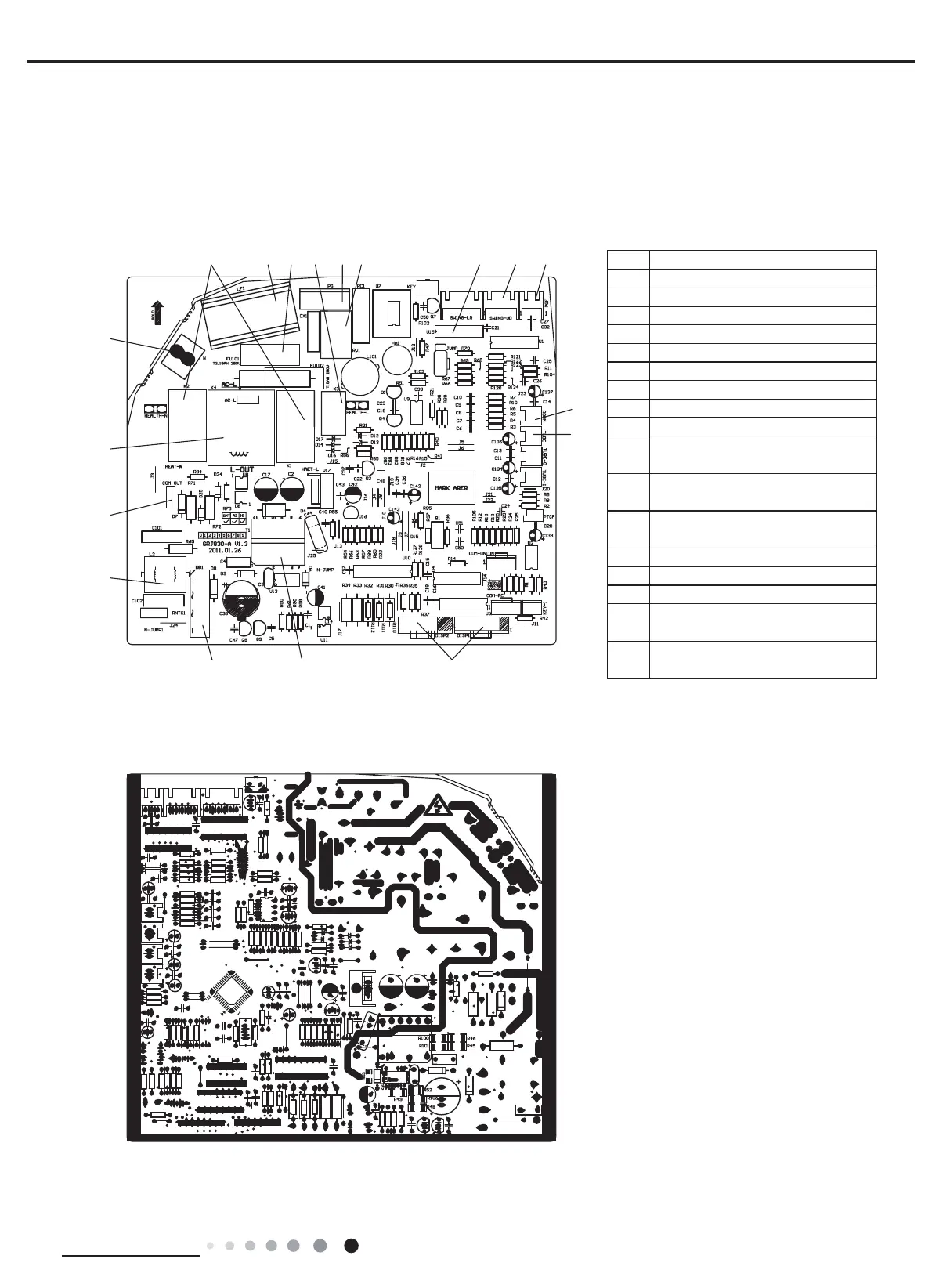
5.2 PCB Printed Diagram
● Top view
● Bottom view
Models:LNINVE052 LNINVE063
Indoor Unit
1 Copper pin terminal of neutral wire
2 Auxiliary heating relay K1, K2
3 Fan capacitor
4 Protective tube
5 Health relay K3
6 PG motor terminal
7 Piezoresistor
8 Jumper cap
9 Up&down swing terminal
10 PG feedback terminal
11
Terminal of ambient temperature
sensor
12
Terminal of tube temperature
sensor
13
Connect display board DISP1,
DISP2 terminals
14 High-frequency transformer T1
15 Rectier DB1
16 Strainer SF2022A-05220
17
Connect copper terminal of
communication line for indoor fan
18
Supply power for control relay K4
of outdoor fan
1
11
12
14
15
16
17
18