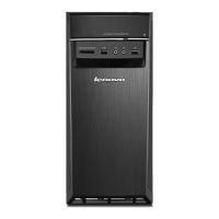
d. Position the heat sink on the M.2 solid-state drive adapter. Ensure that the two mounting studs in the
heat sink are aligned with the holes in the M.2 solid-state drive adapter. Then, push the mounting
studs downward to secure the heat sink to the adapter.
Figure 28. Installing the heat sink
e. Install the M.2 solid-state drive adapter into the appropriate PCIe card slot on the system board. See
“PCIe card” on page 56.
Note: It is recommended that you install the M.2 solid-state drive adapter into the PCIe x16 card
slot. See “Parts on the system board” on page 6.
What to do next:
• To work with another piece of hardware, go to the appropriate section.
• To complete the installation or replacement, go to “Completing the parts replacement” on page 89.
Memory module
Attention: Do not open your computer or attempt any repair before reading and understanding the “Read
this first: Important safety information” on page iii.
Your computer has four memory slots for installing or replacing DDR4 UDIMMs. When installing or replacing
a memory module, use the following guidelines:
• Use any of DDR4 ECC UDIMMs or DDR4 non-ECC UDIMMs for your computer. Do not install the ECC or
non-ECC UDIMMs into the same computer.
• The ECC memory modules are not supported on the computer models with Intel Core i5 or i7
microprocessors.
• Use 4 GB, 8 GB, 16 GB, or 32 GB non-ECC UDIMMs in any combination up to a maximum of 128 GB
system memory.
• Use 8 GB or 16 GB ECC UDIMMs in any combination up to a maximum of 64 GB system memory.
Chapter 7. Hardware removal and installation 65

![Preview: Lenovo F0B2 [C20-30]](https://data.easymanua.ls/products/594284/200x200/lenovo-f0b2-c20-30.webp)