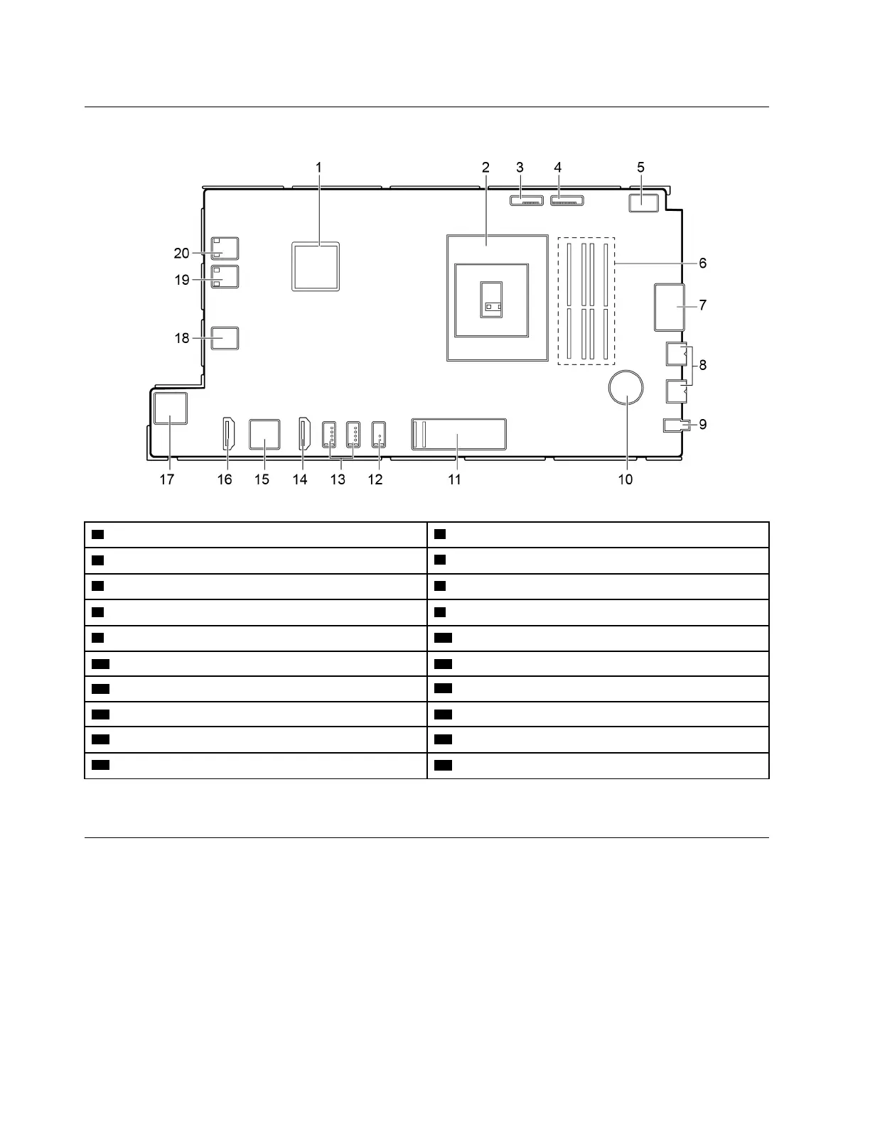
System board
1 GPU
2 Microprocessor socket
3 Converter
4 Integrated camera and microphone module connector
5 M.2 Wi-Fi card slot 6 Memory slot
7 Card reader connector 8 USB 3.1 connector Gen 1/Gen 2* (2)
9 Audio connector
10 CMOS battery
11 M.2 solid-state drive slot
12 USB 3.1 connector Gen 1/Gen 2*
13 USB 2.0 connectors (2)
14 HDMI 1.4 out connector
15 Ethernet connector 16 HDMI 1.4 in connector
17 SATA connector (connecting to the storage drive) 18 LCD LVDS connector
19 Touch board connector
20 System fan connector
* for A540–24ICB models only
Removing and installing hardware
This section provides instructions on how to remove and install hardware for your computer. You can expand
the capabilities of your computer and maintain your computer by removing or installing hardware.
Attention: Do not open your computer or attempt any repair before reading and understanding the Chapter
2 “Important service information” on page 27.
56
IdeaCentre A540-24ICB and A540-24API Hardware Maintenance Manual
 Loading...