14 Components
TIP: See Enclosure bezel attachment and removal on page 56 and Figure 33 on page 57 (2U24).
NOTE: Front and rear panel LEDs for controller enclosures are described in LED descriptions.
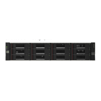
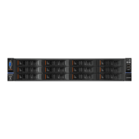
12-drive enclosure front panel components
The geometric representation of 2U12 front panel components is identical for S2200 and S3200.
Figure 2 2U12 enclosure: front panel
TIP: See Enclosure bezel attachment and removal on page 56 and Figure 34 on page 57 (2U12).
NOTE: Front and rear panel LEDs for controller enclosures are described in LED descriptions.
1 Enclosure ID LED
2 Disk drive status LED: Fault
3 Disk drive status LED: Power/Activity
4 3.5" disk or drive blank (typical 12 slots)
5 Enclosure status LED: Unit Locator
6 Enclosure status LED: Fault/Service Required
7 Enclosure status LED: CRU OK
8 Enclosure status LED: Temperature Fault
5
6
7
8
Note: Remove this enclosure bezel to access the front panel components shown below.
21
5
34
6
7
8
Left ear
Right ear
Note: Integers on disks indicate drive slot numbering sequence.
0
4
8
1
5
9
2
6
10
3
7
11
8
6
5
7
(Silk screens on bezel)

 Loading...